

For projects that need precise multi-zone control, strong part-load efficiency, and flexible zoning without a mechanical room full of ductwork, a properly engineered VRF system is often the right HVAC choice. Variable refrigerant flow systems circulate refrigerant directly to indoor units rather than chilled water or ducted air from a central plant, which lets each zone modulate independently while the outdoor unit's inverter-driven compressor tracks the building's actual load in real time.
The design outcome you're after is straightforward to state and harder to execute: correctly sized outdoor equipment, verified piping limits, a defined ventilation strategy, and a controls architecture the owner can actually operate. Get those four things right and VRF delivers on its reputation. Skip verification and lean entirely on manufacturer selection software, and you inherit charge calculations, piping layouts, or combination ratios that look fine on paper and fail on inspection.
VRF tends to be the right call when several of these factors line up on a project:
- Zones have different, sometimes opposing, thermal loads at the same time (a south-facing conference room needing cooling while a north-facing office needs heat).
- Ceiling height or shaft space rules out ducted VAV, favoring compact indoor units.
- The building has retrofit constraints where a chiller plant or new ductwork isn't feasible.
- Occupancy schedules vary by zone (multifamily, hotel guest rooms, multi-tenant office).
- The owner wants metering and zone-level control without a large central plant footprint.
If your project checks three or more of those boxes, the practical next step is to request a candidate VRF layout and preliminary refrigerant charge estimate from an MEP engineer or manufacturer application engineer before committing to a system type. That single deliverable exposes piping length problems, combination ratio mismatches, and code conflicts while they're still cheap to fix.
Table of Contents
- What Is VRF System Design and What Are the Main System Types?
- What Are the Core Components in a VRF System?
- How Do VRF Systems Operate in Real Buildings?
- Sizing Fundamentals: Loads, Capacity Ratio, and Piping Limits
- Ventilation, IAQ, and Humidity: What Design Choices Matter?
- What Controls Strategy Does a VRF Project Need?
- Installation, Commissioning, and Maintenance: What Actually Determines Reliability?
- Where VRF Shines and Where It Doesn't
- Cost Drivers and Timeline: What Should Owners Expect?
- Design Checklist and Spec Snippets Engineers Can Use
- How We Approach VRF Design in Practice
- How Bazini Engineering Supports VRF Projects
- Key Takeaways for Decision-Makers
- Sources
What Is VRF System Design and What Are the Main System Types?
VRF system design is the process of sizing, laying out, and specifying a variable refrigerant flow system so that outdoor condensing equipment, refrigerant piping, indoor units, and controls work together within manufacturer limits and code requirements. The core distinction from conventional DX or chilled-water HVAC is that VRF distributes refrigerant, not water or air, directly to each zone through electronic expansion valves (EEVs) that meter flow independently at every indoor unit. Inverter-driven compressors at the outdoor unit ramp up or down continuously rather than cycling on and off, which is the main driver behind VRF's strong part-load efficiency.
Two major system types define almost every VRF project.
Heat pump systems provide either heating or cooling to the entire connected system at one time. Every indoor unit on that refrigerant circuit runs the same mode. This is the simpler, less expensive configuration and works well for buildings with fairly uniform exposure, like a single-orientation office floor or a small retail space.
Heat recovery systems allow individual indoor units to heat while others on the same outdoor unit cool, using a branch circuit controller (BCC) to redirect refrigerant and transfer heat internally between zones. That internal heat transfer is what makes heat recovery systems noticeably more efficient in mixed-exposure buildings, though it adds cost and a layer of piping (two-pipe systems route liquid and gas lines, three-pipe heat recovery systems add a discharge gas line to the BCC).

A related but separate decision is condenser cooling method. Air-cooled outdoor units dominate the US market and work fine in most climates; water-cooled or water-source VRF shows up in dense urban cores where rooftop space or acoustic limits push designers toward a water loop, or where a building already has a condenser water system to tie into.
You need heat recovery, not a simple heat pump, when a building has real thermal diversity between adjacent zones at the same hour: a hotel with interior corridors next to perimeter guest rooms, a mixed-use building with a ground-floor restaurant kitchen below offices, or a hospital-adjacent outpatient clinic with server rooms next to patient areas. The GSA's VRF guidance report flags this diversity pattern as one of the clearest indicators that heat recovery pays for itself over the building's life.
Pro Tip: Decide heat pump versus heat recovery before you finalize the architectural floor plan, not after. Heat recovery systems need space for BCC boxes above ceilings near each zone cluster, and retrofitting that space in after ceiling heights are locked is one of the most common (and expensive) VRF design corrections.
What Are the Core Components in a VRF System?
Every VRF design revolves around the same handful of components, but the decisions around each one shift depending on building type and layout.
- Outdoor condensing units house the inverter compressors and, in heat recovery systems, connect to the branch circuit controllers. Sizing here drives everything downstream.
- Branch circuit controllers (BCCs) or branch selector boxes route refrigerant between heating and cooling modes in heat recovery systems; they need to sit close to the zones they serve and stay accessible for service.
- Indoor units come in several formats: ceiling cassettes for open-plan offices with exposed grilles, ducted concealed units for tenant fit-outs needing distributed diffusers, high-wall units for budget-driven or retrofit applications, and floor-standing units for perimeter zones with heavy glass load.
- Electronic expansion valves (EEVs) at each indoor unit meter refrigerant flow to match instantaneous zone demand, which is the mechanism behind VRF's zone-level precision.
- Refrigerant piping, headers, and refnet joints distribute liquid and gas lines from the outdoor unit through branch boxes to every indoor unit, sized per manufacturer tables and corrected for length and elevation.
- Signal and communication wiring links indoor units, BCCs, and outdoor units on a proprietary bus, separate from power wiring.
- Oil management components, including traps at vertical risers, keep compressor lubricant circulating properly through long or high-rise piping runs.
Refrigerant distribution deserves its own mention because it's where a surprising number of designs go wrong. Refnet joints (the Y-fittings that split piping into branches) need straight runs before and after the joint, and every joint is a potential leak point that a technician will need to reach again during service. Trane's VRF catalog recommends planning roughly 600 mm of straight, accessible pipe run at each refnet joint, which is a detail that rarely makes it onto architectural reflected ceiling plans unless the MEP engineer flags it early.
On a preliminary schematic, show outdoor unit location and clearances, BCC locations with access panels noted, indoor unit type and capacity per zone, approximate pipe routing with vertical risers called out, and a rough total equivalent length to each indoor unit. That last number is what determines whether the outdoor unit you want will actually work.
Pro Tip: For tenant fit-outs where ceiling space is tight and layouts change between tenants, ducted concealed units paired with flexible branch duct give you the most future flexibility. Ceiling cassettes look cleaner on day one but lock the diffuser location in place for the life of the lease.
Manufacturer selection software is genuinely useful for a first pass at indoor unit combinations, but it will not catch a piping diagram that violates elevation limits or a branch controller placed where nobody can service it. That verification step belongs to the engineer of record, not the software.
How Do VRF Systems Operate in Real Buildings?
VRF systems operate by continuously matching total connected load through inverter compressor modulation and EEV control at each indoor unit, adjusting refrigerant flow rate rather than cycling equipment on and off. The outdoor unit's controller reads demand signals from every connected indoor unit, calculates the aggregate load, and ramps compressor speed to meet it, which is the mechanism behind the efficiency gains you see over fixed-speed DX equipment at partial load.
In a heat recovery system, the behavior gets more interesting. When some zones call for cooling and others call for heat, the BCC redirects refrigerant so the "cooling" zones act like an evaporator and the "heating" zones act like a condenser, moving heat internally between them rather than rejecting it all outdoors. This internal heat transfer is why heat recovery COP figures often look better than heat pump equivalents in mixed-load buildings, a pattern the Wikipedia entry on variable refrigerant flow summarizes alongside the broader efficiency history of inverter-driven VRF equipment.
Defrost cycles matter more in VRF than most engineers coming from packaged DX experience expect. In heating mode during cold weather, outdoor coils ice up periodically and the system reverses briefly to defrost, which can cause a noticeable, if temporary, drop in delivered heat to occupied spaces. Well-designed control logic staggers defrost across multiple outdoor units where possible, and this scheduling directly affects the building's realized IEER and heating COP, not just the nameplate ratings on the equipment.
A few operational failure modes deserve design attention rather than being left to the installer to catch:
- Oil logging in long vertical risers, where oil accumulates in low spots instead of returning to the compressor, gradually starving lubrication.
- Signal interference on the communication bus when control wiring runs parallel to power cabling without separation, causing intermittent faults that look like equipment failure but are actually wiring problems.
- Combination ratio drift when zones are added or changed after initial design without re-verifying the outdoor unit still covers the connected load.
Pro Tip: During commissioning, force a manual defrost cycle and watch how the system recovers across all connected zones, not just the one nearest the outdoor unit. Uneven recovery time usually points to a piping length or elevation issue that the selection software didn't fully account for.
Sizing Fundamentals: Loads, Capacity Ratio, and Piping Limits
Accurate zone-level load calculation is the foundation of every VRF design, and it has to happen before anyone touches manufacturer selection software, not as a check afterward. Software will happily generate a compliant-looking piping diagram around load numbers that are wrong, and the FacilitiesNet coverage of VRF safety standards is blunt about this: sole reliance on manufacturer tools without manual verification is one of the most common sources of non-compliant or unreliable installations.
The selection workflow, in order, looks like this:
- Calculate zone-by-zone heating and cooling loads using standard load software, not rule-of-thumb square footage factors.
- Match indoor units to each zone based on capacity, throw pattern, and available install type.
- Sum indoor unit capacities to get block load, then apply the manufacturer's combination ratio guidance to size the outdoor unit (heat recovery systems often size indoor capacity up to up to roughly 130% of outdoor capacity, using diversity assumptions that not every zone peaks simultaneously, per Budlong's design guidance).
- Lay out refrigerant piping and apply the manufacturer's length and elevation correction factors to confirm the outdoor unit still delivers rated capacity at the actual pipe run, not the catalog-rated run.
- Estimate total refrigerant charge and check it against ASHRAE 15/34 room-volume limits for every space the piping passes through.
Piping constraints are where projects run into trouble, and they vary by manufacturer and system tier. A technical paper on VRF piping design documents systems with total equivalent piping lengths in the 300 to 540 foot range and elevation differences between outdoor and furthest indoor unit reaching 165 to 230 feet, depending on the equipment line and configuration.
| Constraint | Typical range | Design impact |
|---|---|---|
| Total equivalent piping length | 300–540 ft | Longer runs reduce delivered capacity; manufacturer correction factors apply |
| Outdoor to furthest indoor elevation | 165–230 ft | High-rise risers need oil traps and may require charge limits per floor |
| Combination ratio (heat recovery) | up to ~130% | Higher ratios rely on load diversity; verify against actual zone schedules |
| Refnet joint straight-run clearance | ~600 mm minimum | Insufficient clearance creates service access and leak-risk problems |
Here's a short worked example to show how this plays out. Say a floor has ten zones totaling 42 tons of connected indoor capacity in a heat recovery configuration. This is exactly the kind of check that catches problems before procurement, and it's the reason the Specifying Engineer four-step VRF workflow treats preliminary layout and refrigerant charge estimation as inseparable steps rather than sequential ones.
Checklist for design verification before finalizing outdoor unit selection:
- Zone loads calculated independently, not scaled from a master square-footage number.
- Combination ratio confirmed against manufacturer's published maximum for the specific model line.
- Piping length and elevation checked against manufacturer correction tables, not assumed compliant.
- Refrigerant charge estimated and checked room-by-room against ASHRAE 15/34 limits.
- Diversity assumptions documented and defensible if the owner questions comfort complaints later.
Ventilation, IAQ, and Humidity: What Design Choices Matter?
VRF is a refrigerant-based terminal system, and on its own it does not bring in outdoor air or handle latent load in any meaningful way. Almost every code-compliant VRF project needs a separate ventilation strategy, typically a dedicated outdoor air system (DOAS) or energy recovery ventilator (ERV), to meet ASHRAE 62.1 outdoor air requirements and manage humidity.
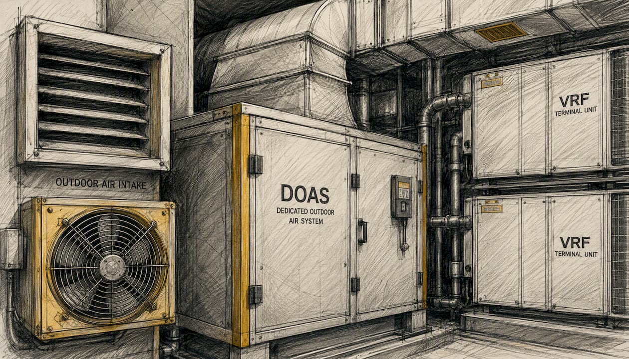
You have two broad paths here. A DOAS with energy recovery pretreats and dehumidifies outdoor air centrally before delivering it to each zone, either ducted directly or tempered and mixed with the VRF's conditioned air. Simple OA kits at individual indoor units are cheaper and simpler but push more of the latent load onto the VRF indoor coil, which was sized for sensible cooling and can struggle to hold space humidity in a hot, humid climate at part load.
That distinction matters more than it sounds like on paper. Trane's VRF product literature recommends deciding on the ventilation and humidity approach at the very start of design, because it changes indoor unit selection, not just the mechanical room layout.
Design checklists differ by application:
- Humid climates: budget for active dehumidification, either DOAS-based or a dedicated terminal reheat coil, rather than relying on the VRF coil alone.
- Museums or archives: specify tighter humidity tolerances than typical office space and verify the DOAS, not the VRF, carries that responsibility.
- Standard office or multifamily: a right-sized DOAS with energy recovery usually covers ventilation and keeps latent load off the VRF indoor units without added terminal equipment.
Pro Tip: Lock your ventilation strategy before finalizing VRF indoor unit selection. Choosing DOAS with full dehumidification up front often lets you downsize indoor units slightly, since they're no longer fighting latent load, which reduces refrigerant charge and helps meet ASHRAE 15/34 room-volume limits without extra leak-detection hardware.
What Controls Strategy Does a VRF Project Need?
Specify the required level of control before you're deep into design development: local-only thermostats, a manufacturer's central VRF controller, or full building automation system (BAS) integration through BACnet or Modbus gateways. This decision affects wiring, gateway hardware, and commissioning scope, and changing it mid-project is expensive.
ASHRAE's Addendum d to Standard 41-2020 makes a point worth internalizing: the minimum controls needed for proper VRF operation should be specified with the VRF equipment package itself, not left as a generic line item in the BAS specification. Manufacturers determine their own required interfaces and proprietary control points, and a BAS contractor guessing at those points after the fact is a recurring source of commissioning delays.
Points to nail down in the specification:
- Manufacturer's minimum required controls package for the selected equipment line.
- Number of gateway points needed per indoor unit for temperature, mode, fault status, and setpoint.
- Alarm and fault reporting format, and whether it routes to the BAS, a manufacturer cloud platform, or both.
- Remote monitoring and analytics requirements, including who owns that data and how long it's retained.
- IT and cybersecurity coordination for any gateway with outside network or cloud access.
Common integration pitfalls worth flagging in review meetings:
- Proprietary control protocols that don't translate cleanly to BACnet without a gateway device, adding cost and a potential point of failure.
- Signal cable routed alongside high-voltage power wiring, causing communication faults that get misdiagnosed as equipment problems.
- BAS integration scoped late, after gateway hardware and point counts were already fixed by the VRF equipment order.
A short BAS point list to request from the manufacturer during submittals: zone temperature and setpoint, operating mode (heat/cool/fan), fault code and alarm status, filter status, and run-hours for maintenance scheduling. Getting this list in writing before equipment order avoids the common scramble where the controls contractor discovers, three weeks before commissioning, that half the points they assumed were available require an add-on gateway module.
Installation, Commissioning, and Maintenance: What Actually Determines Reliability?
Service access, correct manufacturer startup procedure, and refrigerant leak mitigation are the three factors that determine whether a VRF system performs well for fifteen years or generates service calls in year two.
A commissioning checklist for VRF should include, at minimum:
- Refrigerant charge verification against the calculated design charge, not just a "system runs" check.
- Control logic validation across every operating mode, including simultaneous heat/cool for heat recovery systems.
- Oil-return verification at vertical risers and low points in the piping.
- Branch controller settings confirmed against design intent for each zone group.
- Leak-detection sensor placement checked against ASHRAE 15/34 required locations, particularly in smaller occupied rooms.
- Fault logging and alarm reporting confirmed functional end to end, from indoor unit to BAS or manufacturer platform.
Field installation practices that prevent the most common warranty claims:
- Proper pipe support at manufacturer-specified intervals prevents sagging that stresses joints over time.
- Signal cable kept physically separated from power cabling, per manufacturer wiring diagrams, avoids communication faults.
- Refnet joints installed with full straight-run clearance and located where a technician can actually reach them later.
- Correct slope and trap details at vertical risers ensure oil returns to the compressor rather than pooling.
Maintenance planning should be part of the design deliverable, not an afterthought handed to the owner at closeout. Recommend service intervals aligned with manufacturer guidance, identify long-lead spare parts (control boards, EEV assemblies), and confirm the owner's facilities staff receive manufacturer training on the specific equipment line installed, not generic VRF training.
Pro Tip: The single most common warranty dispute on VRF projects traces back to refrigerant charge documentation. Require the installing contractor to submit a signed charge log by circuit, with the calculated design charge alongside the as-built charge, before final commissioning sign-off.
Where VRF Shines and Where It Doesn't
VRF fits naturally into office fit-outs, hotels, multifamily buildings, and selective retrofit projects where ductwork or a chilled water plant isn't practical.
Trade-offs worth disclosing to an owner during early design conversations:
- First cost versus lifecycle cost: VRF equipment and controls typically cost more upfront than packaged rooftop units, but recover that gap over time through part-load efficiency, particularly in buildings with real load diversity.
- Refrigerant risk in occupied spaces: ASHRAE 15/34 room-volume rules can force smaller rooms into a subdivided system design, transfer air openings, or added leak detection, which the Specifying Engineer four-step workflow treats as a mandatory design step rather than an optional safety margin.
- Maintenance skill requirements: VRF service technicians need manufacturer-specific training; a facilities team used to packaged rooftop units will need a learning curve or a service contract.
- Acoustic considerations: indoor units, particularly ducted concealed types at higher static pressure, can introduce noise that needs review against space acoustic criteria.
Quick guidance by building profile: smaller commercial spaces with straightforward zoning often do fine with a simple heat pump VRF and packaged DOAS. Mixed-use or multifamily buildings with real thermal diversity between units usually justify heat recovery despite the added cost.
Pro Tip: A hybrid of VRF plus DOAS covers the majority of commercial and multifamily applications well. VRF paired with a central hydronic plant makes sense mainly in campus settings where the plant already exists and VRF is filling gaps in a renovation, not replacing the whole system.
Cost Drivers and Timeline: What Should Owners Expect?
The primary cost drivers on a VRF project are system type (heat recovery costs more than heat pump), refrigerant piping complexity and length, the number of branch controllers required, and whatever DOAS or ventilation upgrades the project needs to meet code. None of these show up clearly on a per-square-foot budget estimate pulled from a past project with a different layout.
High-level project milestones, roughly in sequence: equipment selection and submittal review, manufacturer procurement and factory assembly (often the longest lead-time item), onsite rough-in piping and electrical, equipment set and refrigerant charging, and commissioning. Lead times for VRF equipment can run considerably longer than packaged rooftop units because of the custom combination of outdoor units, branch controllers, and indoor unit types specific to each project.
Statistic callout: Piping and elevation constraints alone can shift equipment selection by a full outdoor unit size when total equivalent length approaches the upper length limits documented in VRF piping research (https://oaktrust.library.tamu.edu/bitstream/handle/1969.1/5243/ESL-IC-06-11-104.pdf?sequence=4&isAllowed=y), which is a budget swing worth catching during schematic design rather than after equipment order.
On procurement, coordinate the manufacturer's application engineer, the installing contractor, and the commissioning agent early and keep them talking through the piping design phase, not just at kickoff and closeout. This single practice prevents the most common source of delay: a piping layout finalized by the installer that doesn't match what the manufacturer's software assumed during equipment selection.
Critical path items to watch on the schedule: structural rooftop work if the outdoor units require curb modifications or added roof support, electrical service upgrades for the outdoor unit's power requirements, and refrigerant handling permits, which vary by jurisdiction and can add unexpected lead time if not identified during preliminary design.
Design Checklist and Spec Snippets Engineers Can Use
Before equipment selection locks in, confirm these decisions are documented and signed off: ventilation strategy (DOAS scope and energy recovery type), humidity targets by space type, combination ratio assumptions, piping length and elevation limits by manufacturer, and refnet and branch controller locations on the reflected ceiling plan.
Spec-language snippets worth adapting into your own project documents:
- Refrigerant piping installation: "All refrigerant piping shall be installed per manufacturer's published length and elevation correction tables. Contractor shall submit as-built piping isometrics with total equivalent length calculations for engineer review prior to refrigerant charging."
- Branch circuit controller access: "BCC units shall be installed with a minimum 24-inch clear access panel and shall not be located in inaccessible ceiling cavities or above fixed millwork."
- Controls gateway requirements: "VRF manufacturer shall provide a BACnet or Modbus gateway capable of reporting zone temperature, operating mode, fault status, and filter status to the building automation system for each connected indoor unit."
- Refrigerant leak detection and alarms: "Leak detection sensors shall be installed per ASHRAE 15/34 requirements based on calculated refrigerant charge per circuit and room volume, with alarm output routed to the BAS and local audible/visual alarm."
Required submittal deliverables to request from the manufacturer or their rep during design development:
- Pipe sizing tables showing selected pipe diameter at every branch and riser.
- Calculated refrigerant charge per circuit, broken out by room for ASHRAE 15/34 verification.
- Selection software output showing combination ratio and capacity correction factors applied.
- Control point list confirming what's available for BAS integration without additional gateway hardware.
Pro Tip: Request the manufacturer's selection software output as a PDF, not just a summary email. That documentation becomes your record during commissioning disputes and gives the installing contractor a clear target to build against.
How We Approach VRF Design in Practice
VRF looks deceptively simple in a manufacturer's marketing brochure: pick some indoor units, connect them to an outdoor unit, done. The reality on every project we've worked through is that the decisions made in the first two weeks of design, ventilation strategy, combination ratio assumptions, and where branch controllers physically sit, determine whether the system performs for fifteen years or generates a steady stream of service calls starting in year two.
Our approach treats manufacturer selection software as a starting point, never a final answer. We verify piping length and elevation against the actual architectural layout, not a simplified stick diagram, because that's where charge calculations and correction factors go wrong most often. On refrigerant safety, we'd rather subdivide a system or add a transfer air path during design than discover during commissioning that a small conference room violates ASHRAE 15's room-volume limit for the calculated charge.
Our default preference, absent a compelling reason otherwise, is DOAS-based ventilation with energy recovery, decided before indoor unit selection locks in. It keeps latent load off VRF terminal units, which lets us right-size equipment instead of oversizing to compensate for humidity the VRF was never going to handle well on its own.
How Bazini Engineering Supports VRF Projects
Getting VRF right on paper is one thing. Getting it through NYC Department of Buildings review, permitted, and commissioned without change orders is a different challenge entirely, and it's where a firm that handles both the mechanical design and the code coordination earns its fee. Bazini Engineering provides HVAC system design, refrigerant charge verification, controls specification, and commissioning support for VRF projects across New York City, Long Island, and Westchester County, working directly with manufacturer application engineers so the piping diagrams and combination ratios hold up under scrutiny, not just under selection software defaults.

If your project also touches Local Law 97 compliance, plumbing coordination, or fire protection systems that need to work around a VRF layout, that's within scope too, since MEP/FP disciplines rarely stay siloed on a real building. The firm's service offerings cover code compliance review, specification writing, and permit expediting alongside the mechanical design itself, which cuts down on the coordination gaps that show up when separate consultants hand off a project without talking to each other.
If you're evaluating VRF for an upcoming project, the practical next step is requesting a scoped assessment: a preliminary layout review, a refrigerant charge estimate, and sample spec language you can bring into your next design meeting.
Key Takeaways for Decision-Makers
VRF succeeds when zone-level loads are calculated accurately, piping limits are verified against manufacturer data, ventilation is planned as a separate system, and controls scope is locked in before equipment order.
| Point | Details |
|---|---|
| Verify loads independently | Calculate zone-by-zone loads before running manufacturer selection software, not after. |
| Check piping and elevation limits | Confirm total equivalent length and elevation against manufacturer correction tables during schematic design. |
| Plan ventilation separately | Decide on DOAS or ERV strategy before finalizing indoor unit selection to manage humidity properly. |
| Lock controls scope early | Specify local, central, or full BAS integration before equipment procurement to avoid gateway rework. |
| Engage MEP support for verification | Bazini Engineering reviews piping layouts, refrigerant charge, and controls specifications for VRF projects in the New York City area. |
Sources
Designers specifying VRF systems should keep a handful of primary references close at hand rather than relying on manufacturer marketing alone.
For project-specific guidance, including sample spec language and a preliminary layout review, Bazini Engineering's homepage has contact details and a full breakdown of MEP/FP services available for projects across the New York City region.