
TL;DR:
- Seismic braces support mechanical, electrical, and plumbing systems during earthquakes by resisting lateral and vertical forces. Proper design, installation, and early coordination are essential to prevent costly field conflicts and ensure safety. Compliance with standards like ASCE 7-22 is mandatory for high-risk zones and critical facilities.
A seismic brace for MEP is a structural support device that restrains mechanical, electrical, and plumbing components against lateral and vertical forces generated during an earthquake. Unlike standard pipe hangers or conduit supports, which carry only gravity loads, seismic braces are engineered to hold systems in place when the ground moves. The industry term is "seismic restraint," and it covers every brace, anchor, and attachment that keeps MEP utilities from swinging, collapsing, or rupturing during a seismic event. Governing standards like ASCE 7-22 and NFPA 13 define where these restraints are mandatory and how they must perform. Getting seismic bracing right is not optional in high-risk zones. It is a code requirement, a life-safety obligation, and a coordination challenge that starts at the design table.
What is a seismic brace for MEP, and why does it matter?
A seismic brace secures MEP components so they do not become projectiles or fail during ground shaking. Non-structural MEP utilities secured with seismic braces reduce the risk of operational disruption, property damage, and occupant hazards during earthquakes. That last point deserves emphasis: unbraced ductwork, piping, and conduit can collapse onto evacuation routes, rupture gas lines, or knock out fire suppression systems at the worst possible moment.

Seismic braces serve a fundamentally different purpose than conventional supports. Seismic bracing resists both lateral and vertical forces, while conventional supports primarily carry static gravity loads. That distinction drives every design decision, from material selection to attachment angle to anchor bolt sizing. A standard threaded rod hanger keeps a pipe from falling under its own weight. A seismic brace keeps that same pipe from swinging six inches sideways and shearing at a joint.
The seismic brace purpose extends beyond protecting the pipe itself. Braced systems preserve building functionality after an event, which is why hospitals, data centers, and emergency response facilities face the strictest requirements. A building that survives a magnitude 6.5 earthquake but loses water pressure or electrical power for three days has still failed its occupants.
What types of seismic braces are used in MEP systems?
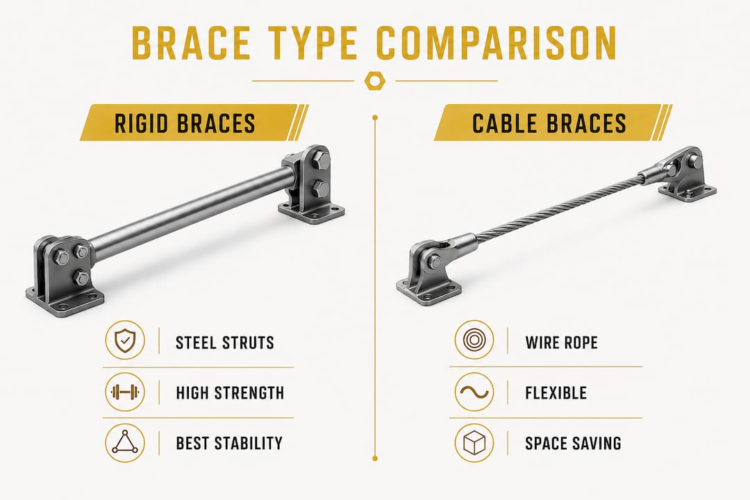
Three primary brace types appear across MEP seismic design: rigid braces, cable braces, and threaded rod assemblies. Each handles seismic forces differently, and each suits specific system types and spatial conditions.
Rigid braces
Rigid braces use steel struts, angles, or channel sections installed diagonally between the MEP component and the building structure. They transfer seismic loads directly and with minimal deflection. Rigid braces work well for heavy equipment, large-diameter piping, and ductwork where stiffness is the priority. The tradeoff is that they occupy more plenum space and require precise alignment during installation.
Cable braces
Cable bracing uses high-strength wire rope or aircraft cable installed in an X-pattern or single-diagonal configuration. Cables absorb and dissipate seismic energy through controlled elastic deformation. They are lighter than steel struts and easier to route around obstructions, making them popular for electrical conduit runs and smaller piping. Proper cable brace tensioning is critical: the cable must remove all slack but must not be over-tightened, since pre-load damage can compromise the pipe or fitting before any earthquake occurs.
Threaded rod assemblies
Threaded rod assemblies combine standard hanger rods with seismic-rated clevis brackets, sway braces, and structural attachments. They are the most common solution for suspended piping because they integrate with existing hanger systems. The rod itself carries gravity load, while the diagonal sway brace component handles lateral forces. Proper attachment hardware at both the structural anchor and the pipe clamp is what makes the system perform as designed.
Pro Tip: Never substitute standard pipe clamps for seismic-rated clamps on a braced assembly. The clamp is the weakest link in the load path, and an undersized clamp will fail before the brace does.
The table below summarizes how each brace type compares across key design factors.
| Brace type | Primary load path | Best application | Space impact |
|---|---|---|---|
| Rigid steel strut | Direct compression/tension | Heavy pipe, large duct, equipment | High |
| Cable brace | Tension with energy dissipation | Conduit, small pipe, light duct | Low to moderate |
| Threaded rod assembly | Combined gravity and lateral | Suspended piping systems | Moderate |
What are the key seismic design code requirements for MEP braces in 2026?
Code compliance for MEP seismic bracing runs through three primary documents: ASCE 7-22, the International Building Code (IBC), and NFPA 13 for fire protection systems. Healthcare projects in California add a fourth layer through HCAi, formerly known as OSHPD.
ASCE 7-22 mandates seismic restraint for nearly every piece of MEP equipment in Seismic Design Categories D, E, and F. SDC D covers most of the western United States and parts of the central and eastern regions near active fault zones. SDC E and F apply to essential facilities like hospitals and emergency operations centers in high-hazard areas. The higher the SDC, the more prescriptive the bracing requirements become, including engineered calculations rather than catalog solutions.
The Component Importance Factor (Ip) is a multiplier that increases design forces for critical systems. An Ip of 1.5 applies to life-safety systems, hazardous material containment, and components in essential facilities. That factor directly increases the required brace capacity, which means a hospital HVAC unit in SDC D needs a stronger brace than an identical unit in a standard office building in the same zone.
Key mandatory bracing locations under current standards include:
- Changes in pipe or duct direction greater than 12 inches
- Pipe and duct ends (free ends are the most vulnerable points)
- Riser connections at each floor
- Every 30–40 feet along horizontal runs
- Equipment connections where vibration isolation mounts are used
NFPA 13 requires sway bracing for fire sprinkler piping 2-1/2 inches and larger, with spacing requirements that closely align with general MEP seismic brace intervals. This alignment matters for coordination: a sprinkler brace and an HVAC brace competing for the same structural attachment point is a common field conflict that must be resolved at the design stage, not during installation.
HCAi requirements go further than ASCE 7-22 for California healthcare projects. They require project-specific seismic calculations, third-party review, and documentation that standard catalog brace schedules cannot satisfy on their own. Engineers working on hospital projects in California need to treat seismic bracing as a primary design deliverable, not a specification afterthought.
How are seismic braces installed and coordinated in MEP system designs?
Installation quality determines whether a seismic bracing system performs as designed or fails at the first significant ground motion. The engineering is only as good as the field execution.
Follow this sequence for reliable seismic brace installation:
- Confirm structural attachment capacity. Verify that the deck, beam, or concrete slab can accept the calculated seismic load at each anchor point. Anchor bolt pullout strength governs many failures, not the brace itself.
- Set brace spacing before running pipe or duct. Mark brace locations on the structural drawings before fabrication begins. Retrofitting brace points after a system is installed costs significantly more time and money.
- Install at mandatory locations first. Place braces at pipe ends, direction changes, and risers before filling in the intermediate spacing. These points carry the highest seismic demand.
- Tension cable braces correctly. Remove all slack from cable assemblies using a calibrated tensioning tool. Stop before the cable begins to deflect the pipe off its design centerline.
- Inspect clamp and fitting torque. Every seismic-rated clamp has a manufacturer-specified torque value. Under-torqued clamps slip during a seismic event. Over-torqued clamps crack pipe coatings and reduce clamping force.
- Document as-built brace locations. Record actual installed brace positions, especially where field conditions required deviations from the design drawings. This documentation supports inspection and future renovation work.
Seismic lateral braces should be installed at changes in direction, pipe ends, risers, and every 30–40 feet along the run. That spacing rule applies to most piping and duct systems, but always verify against the project-specific brace schedule, since larger pipe diameters and higher Ip values can tighten the interval.
Pro Tip: Coordinate brace attachment points with the structural engineer before the concrete deck is poured or the steel is erected. Adding post-installed anchors in a congested plenum costs three to five times more than cast-in-place inserts.
The plenum space impact of diagonal bracing is one of the most underestimated coordination challenges in MEP seismic design. Brace geometry can occupy 18–24 inches of plenum space per attachment point at a 30–45 degree angle. That footprint extends beyond the pipe or duct centerline in every direction, which means a 6-inch pipe with a seismic brace effectively claims a 3-foot-wide corridor of ceiling space. Early BIM coordination is the only reliable way to catch these conflicts before they become field problems.
What are common challenges in MEP seismic bracing coordination?
Seismic bracing coordination fails most often because of three recurring problems: geometry conflicts in the plenum, inconsistent design data across documents, and late integration with other trades.
Seismic braces extend diagonally 18–24 inches off pipe or duct centerline at 30–45 degree angles. Most engineers model the pipe or duct correctly but omit the brace geometry from the coordination model. The result is a brace that physically cannot be installed because a structural beam, light fixture, or adjacent duct occupies the space the brace needs. Catching this in a 3D BIM model costs hours. Catching it in the field costs days.
Consistency in Seismic Design Category and Importance Factor across structural and MEP documents is the single most common source of permit delays and rework. When the structural engineer assigns SDC D to a building and the MEP engineer uses SDC C in the brace schedule, the permit reviewer will reject the submission. Resolving that conflict after permit submission can delay a project by weeks.
Effective coordination requires these practices:
- Integrate seismic brace geometry into the 3D BIM model from the schematic design phase, not during construction documents
- Confirm SDC and Ip values with the structural engineer before the MEP brace schedule is drafted
- Coordinate brace attachment points with the structural team to avoid conflicts with beams, joists, and post-installed anchor zones
- Align sprinkler brace locations with HVAC and plumbing brace points where possible to share structural attachments
- Document all field exceptions with engineering approval before installation proceeds
Good subcontractor coordination practices also apply directly here. When multiple MEP trades are installing braces in the same plenum, a clear coordination protocol prevents the most common field conflicts. Assign one trade lead to own the brace coordination model and require all others to submit clash reports before installation begins.
Seismic bracing must be integrated into 3D BIM models early to avoid costly clashes with other trades and structural elements. That is not a suggestion. On complex projects, late brace coordination is one of the top three causes of schedule overruns in the MEP scope.
Key Takeaways
Seismic braces for MEP systems are code-mandated structural supports that resist lateral and vertical earthquake forces, and their design, spacing, and coordination must be resolved before construction begins.
| Point | Details |
|---|---|
| Seismic braces vs. standard supports | Seismic braces resist lateral and vertical forces; standard hangers carry gravity loads only. |
| ASCE 7-22 mandate | SDC D, E, and F projects require engineered seismic restraint for nearly all MEP equipment. |
| Brace spacing rule | Install braces at pipe ends, direction changes, risers, and every 30–40 feet along horizontal runs. |
| Plenum space impact | Diagonal braces claim 18–24 inches of ceiling space beyond the pipe centerline at each point. |
| BIM coordination timing | Model seismic brace geometry in 3D from schematic design to prevent costly field conflicts. |
Why seismic bracing deserves more attention than it gets
Seismic bracing is one of those topics that engineers treat as a specification checkbox until they work on a project where it goes wrong. I have seen brace schedules submitted with the wrong SDC, cable assemblies installed with visible slack, and entire plenum coordination models that did not include a single brace element. Each of those failures is preventable, and each one is expensive to fix after the fact.
What has changed significantly with ASCE 7-22 is the expectation that seismic restraint is an engineered deliverable, not a catalog selection. Seismic brace design has evolved to include advanced engineered solutions tailored for healthcare and critical infrastructure projects. That evolution reflects real lessons from post-earthquake building assessments, where unbraced MEP systems caused more operational disruption than structural damage in many cases.
The practical lesson I keep coming back to is this: seismic bracing coordination belongs in the project kickoff meeting, not the construction administration phase. When the structural engineer, MEP engineer, and BIM coordinator align on SDC, Ip values, and attachment zones before the first drawing is issued, the entire brace design process runs faster and produces fewer field conflicts. The technology to do this well, specifically clash-detection in BIM platforms, exists and is widely available. The barrier is not technical. It is a project management habit of treating seismic bracing as someone else's problem until it becomes everyone's problem.
— Joseph
Baziniengineering's approach to MEP seismic design
Seismic bracing compliance requires more than selecting the right catalog brace. It requires coordinated engineering across mechanical, plumbing, and fire protection systems from the earliest design phase.

Baziniengineering brings that coordination discipline to every project. The firm's MEP engineering services cover seismic restraint design for HVAC, plumbing, and fire suppression systems, with direct experience applying ASCE 7-22 requirements across commercial, institutional, and healthcare projects in New York and Florida. Whether you are working through an SDC D brace schedule or coordinating a complex hospital plenum, Baziniengineering provides the engineering support to get it right the first time. Contact the team to discuss your project's seismic bracing requirements.
FAQ
What is a seismic brace for MEP systems?
A seismic brace for MEP is a structural support that restrains mechanical, electrical, and plumbing components against lateral and vertical forces during an earthquake. It differs from standard pipe hangers, which carry only gravity loads.
Which seismic design categories require MEP bracing?
ASCE 7-22 mandates seismic restraint for MEP systems in Seismic Design Categories D, E, and F. Healthcare projects in California face additional requirements under HCAi.
How far apart should seismic braces be spaced?
Seismic lateral braces should be installed every 30–40 feet along horizontal runs, and at all pipe ends, direction changes, and riser connections.
Does NFPA 13 require seismic bracing for sprinkler systems?
NFPA 13 requires sway bracing for fire sprinkler piping 2-1/2 inches and larger, with spacing that aligns closely with general MEP seismic brace intervals.
Why does brace geometry matter for ceiling coordination?
Diagonal seismic braces extend 18–24 inches off the pipe or duct centerline at 30–45 degree angles, consuming significant plenum space that must be accounted for in BIM coordination models before installation begins.