

TL;DR:
- Pipe sizing in plumbing design involves selecting the correct pipe diameter to ensure proper flow and pressure at all fixtures. It combines demand estimation using fixture units with hydraulic calculations for pressure loss, following code standards. Accurate sizing requires considering actual internal diameters, friction loss, slope, and local code requirements.
Pipe sizing in plumbing design is the process of selecting the correct nominal pipe diameter so that every fixture in a building receives adequate flow and pressure while wastewater drains reliably by gravity. Engineers and plumbers use fixture unit methods and hydraulic calculations to translate probable demand into specific pipe diameters, all within the boundaries set by the International Plumbing Code (IPC) and local amendments. Get the diameter wrong in either direction and the consequences range from noisy pipes and pressure complaints to code violations and costly rework. This guide covers the full process: fixture units, friction loss, supply versus drainage differences, common pitfalls, and real-world application.
What is pipe sizing in plumbing design?
Pipe sizing selects the nominal pipe diameter that satisfies required flow rate, allowable pressure loss, and code compliance at the most remote fixture in the system. The word "nominal" matters here. Nominal pipe size (NPS) is a catalog label, not a physical measurement. A 1-inch nominal copper pipe does not have a 1-inch internal bore. Every hydraulic calculation must use the actual internal diameter, not the nominal label.

The process sits at the intersection of two disciplines: demand estimation and hydraulic analysis. Demand estimation answers the question of how much water the system must carry at peak load. Hydraulic analysis answers whether the pipe can carry that water without losing too much pressure along the way. Neither discipline alone produces a reliable design.
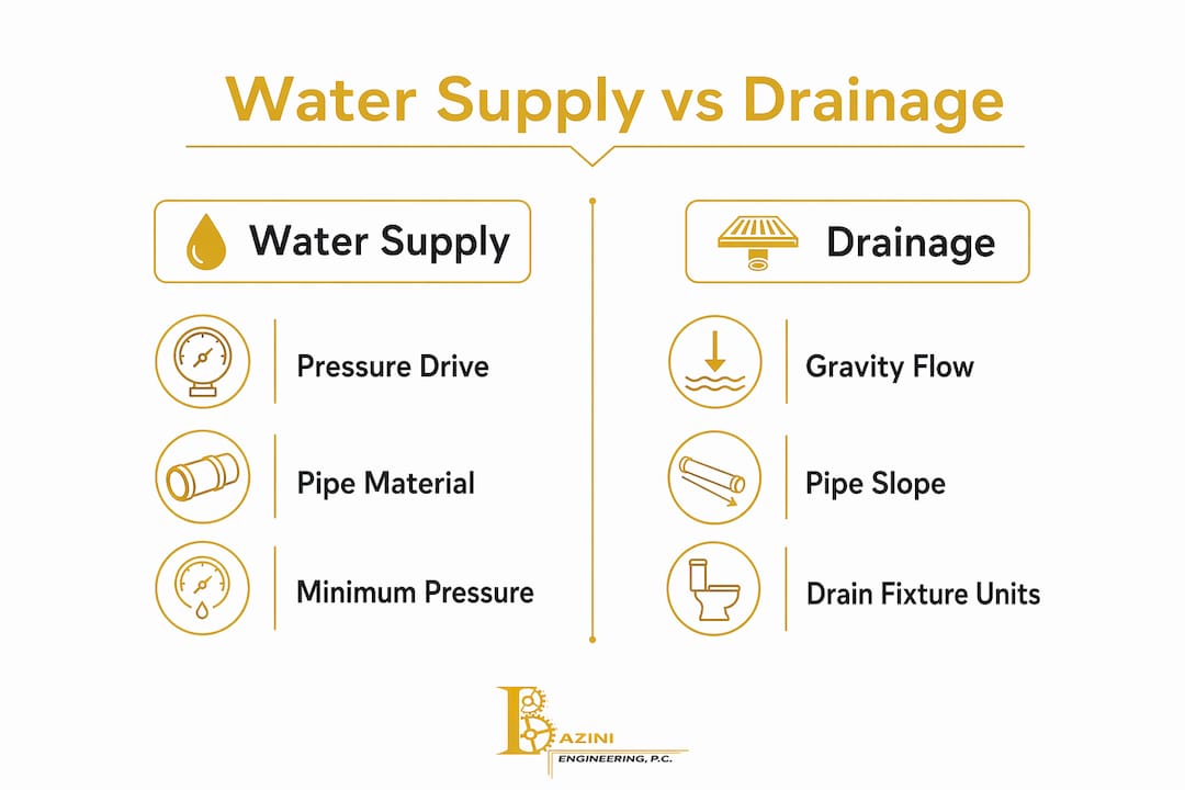
Plumbing design basics require that both supply and drainage systems be sized independently, using different code tables, different unit systems, and different physical principles. Supply pipes operate under pressure. Drainage pipes rely on gravity. The sizing logic for each reflects that fundamental difference.
What are fixture units and how do they influence pipe sizing?
Fixture units are the foundation of demand estimation in plumbing design. The IPC assigns a Water Supply Fixture Unit (WSFU) value to every plumbing fixture based on its probable simultaneous demand. A standard lavatory faucet carries 1 WSFU. A bathtub carries 2 WSFU. A flush valve water closet carries 6 WSFU. These values reflect statistical probability, not peak instantaneous flow.
The sizing process using fixture units follows a clear sequence:
- Sum the fixture units for every fixture served by the pipe segment being sized.
- Convert total WSFU to design flow in GPM using the IPC's demand load curve or equivalent code table.
- Select a pipe diameter from the code's pressure loss tables that carries the design GPM within the allowable pressure drop per 100 feet of pipe.
- Verify pressure at the most remote fixture after accounting for elevation, friction, and fittings.
- Repeat for each segment from the meter to the farthest outlet.
The conversion from fixture units to GPM is nonlinear. Adding more fixtures does not add proportionally more flow because not all fixtures run simultaneously. This is the statistical insight that makes fixture units practical. A building with 100 lavatories does not need a pipe sized for 100 simultaneous flows.
Drain Fixture Units (DFU) follow the same logic for drainage systems. The IPC assigns DFU values separately from WSFU values, and the drainage sizing tables are distinct from supply tables.
Pro Tip: When sizing a branch serving both a toilet and a lavatory, always check whether the toilet's minimum mandatory diameter overrides the fixture unit calculation. The IPC requires a minimum 3-inch drain for a water closet regardless of the DFU count.
How does hydraulic friction affect pipe diameter calculations?
Friction loss is the pressure that a flowing fluid loses to resistance inside the pipe. Every foot of pipe, every elbow, every valve, and every change in elevation consumes available pressure. The Hazen-Williams equation is the standard tool for calculating this loss in water supply systems.
The equation relates four variables: flow rate (GPM), pipe internal diameter (inches), pipe roughness coefficient (C), and friction head loss per unit length. The critical insight is that friction loss varies approximately with pipe diameter raised to the power of 4.87. That nonlinear relationship means a small reduction in diameter produces a large increase in pressure loss. Dropping from a 1.5-inch pipe to a 1.25-inch pipe on a long run can more than double the friction loss.
| Variable | What it represents | Typical value |
|---|---|---|
| Q (flow rate) | Design GPM from fixture unit conversion | Varies by segment |
| D (internal diameter) | Actual bore of the pipe, not nominal size | Varies by material |
| C (roughness coefficient) | Pipe smoothness; higher C means less friction | Copper: 130–150, Steel: 100–120 |
| hf (friction head loss) | Pressure lost per 100 feet of pipe | Design limit per code |
Fittings add friction equivalent to additional pipe length. A 90-degree elbow on a 1-inch copper pipe adds roughly 1.5 feet of equivalent length. A gate valve adds less than 1 foot. A swing check valve adds over 5 feet. Engineers calculate the total "developed length" of a segment by adding actual pipe length to the equivalent lengths of all fittings and valves in that segment.
Pro Tip: Always size for the critical path, which is the route from the water meter to the most remote and most demanding fixture. If that path meets pressure requirements, every shorter path will too.
What are the key differences between sizing water supply and drainage pipes?
Supply and drainage pipes operate under entirely different physical conditions. Understanding those differences prevents the most common design errors.
| Design factor | Water supply pipes | Drainage pipes |
|---|---|---|
| Driving force | Pressure from utility or pump | Gravity |
| Unit system | Water Supply Fixture Units (WSFU) | Drain Fixture Units (DFU) |
| Key constraint | Pressure loss and velocity limits | Slope and self-cleansing velocity |
| Minimum diameter | Set by pressure loss calculation | Set by fixture type (e.g., 3-inch for toilets) |
| Code tables used | IPC Table 604.3 (supply sizing) | IPC Table 710.1 (drainage sizing) |
| Flow direction | Pressurized, any orientation | Downhill, slope-dependent |
Drain pipe sizing relies on gravity flow, so slope is as critical as diameter. The IPC requires a minimum slope of 1/4 inch per foot for pipes 3 inches and smaller. A pipe with the correct diameter but insufficient slope will allow solids to settle, leading to blockages. Drainage pipe sizing is inseparable from slope design because solids transport depends on adequate velocity, not just pipe bore.
Supply pipes must maintain pressure at the most remote fixture. The IPC typically requires a minimum of 15 psi at most fixtures and 20 psi at flush valve water closets. Every foot of elevation the water must rise costs 0.433 psi. A fixture 20 feet above the meter loses nearly 9 psi to elevation alone before friction is even considered.
What practical design considerations affect pipe sizing accuracy?
Velocity is the variable that most engineers check last and should check first. Velocity limits in water supply systems sit around 2 ft/s to prevent noise, erosion, and water hammer. Minimum velocity for drainage self-cleansing is approximately 0.6 m/s (about 2 ft/s). Both limits point to the same number, but for opposite reasons: supply pipes must stay below it to avoid noise, and drainage pipes must stay above it to move solids.
Common pitfalls that produce inaccurate pipe sizing include:
- Using nominal diameter in hydraulic formulas. The nominal pipe size is a catalog label. Hydraulic calculations require the actual internal diameter, which varies by material, schedule, and manufacturer. Copper Type L and Type K have different wall thicknesses and therefore different internal diameters at the same nominal size.
- Ignoring fittings in developed length. A segment with many elbows and valves can have an equivalent length two to three times its physical length. Skipping this step underestimates friction loss.
- Oversizing to be safe. Oversizing pipe wastes material, increases cost, and creates stagnation risk in domestic hot water systems where water sits in large-bore pipes and cools before reaching the fixture.
- Undersizing to save cost. Undersizing raises velocity above limits, increases friction loss, and produces pressure failures at remote fixtures.
- Applying supply tables to drainage. The two systems use different fixture unit scales and different code tables. Mixing them produces unreliable results.
- Skipping the iterative check. A first-pass diameter from a fixture unit table is a starting point, not a final answer. Every segment needs a hydraulic check.
Two systems with equal total fixture units may require different pipe sizes because routing, developed length, and pressure loss vary with building layout. The fixture unit table gives you a candidate diameter. The hydraulic analysis confirms or corrects it.
How to apply pipe sizing principles in real-world plumbing design projects?
A practical sizing workflow for a residential building water supply follows a consistent sequence. The steps below apply to a four-story apartment building with 12 units, each containing a kitchen sink, lavatory, bathtub, and toilet.
- List all fixtures and assign WSFU values. Each unit has approximately 6 WSFU (1 for lavatory, 2 for bathtub, 1 for kitchen sink, 2 for toilet with tank). Twelve units total 72 WSFU for the building main.
- Convert total WSFU to design GPM. Using the IPC demand load curve, 72 WSFU converts to approximately 40 GPM for the building main.
- Determine available pressure. The utility delivers 65 psi at the meter. The top floor is 40 feet above the meter, consuming 17.3 psi to elevation. The pressure regulating valve (PRV) and meter account for roughly 10 psi. Available pressure for friction loss in the main is approximately 37.7 psi.
- Calculate allowable friction loss per 100 feet. If the critical path from meter to top-floor fixture is 120 feet of developed length, the allowable friction loss is 37.7 psi divided by 1.2, or about 31 psi per 100 feet.
- Select pipe diameter using Hazen-Williams. At 40 GPM with a copper C-factor of 140 and 31 psi per 100 feet allowable, a 2-inch copper main satisfies the criteria.
- Size branch pipes by the same method. Each floor branch serves three units (18 WSFU, roughly 14 GPM). A 1.5-inch branch pipe handles this load within velocity and pressure limits.
- Check drainage separately. Each unit's drain stack collects DFU values from all fixtures. The IPC table sets minimum stack diameter at 3 inches for any stack serving a toilet. Verify slope at 1/4 inch per foot for all horizontal branches.
- Iterate if any segment fails the velocity or pressure check. Increase diameter by one standard size and recheck. Repeat until all segments pass.
Fixture unit methods simplify complex simultaneous demand estimation, enabling conservative and practical designs without detailed flow scenario modeling. The hydraulic check then confirms that the candidate diameters actually deliver adequate pressure.
Key takeaways
Pipe sizing in plumbing design requires combining fixture unit demand estimation with segment-by-segment hydraulic analysis to select diameters that satisfy both flow and pressure requirements at every fixture.
| Point | Details |
|---|---|
| Fixture units drive demand estimates | Sum WSFU or DFU per segment, then convert to GPM using IPC code tables before selecting a diameter. |
| Hazen-Williams governs friction loss | Use actual internal diameter and the correct C-factor for your pipe material to calculate pressure drop accurately. |
| Supply and drainage use separate methods | Supply pipes follow pressure-driven sizing; drainage pipes follow gravity, slope, and minimum diameter rules. |
| Velocity limits apply to both systems | Keep supply velocity below 2 ft/s to prevent noise and erosion; keep drainage velocity above 0.6 m/s for self-cleansing. |
| Nominal size is not internal diameter | Always use the actual bore in hydraulic formulas. Using nominal size produces incorrect pressure loss estimates. |
What I've learned from years of pipe sizing on real projects
The most persistent mistake I see in plumbing design is treating the fixture unit table as the finish line. Engineers pull a diameter from the IPC table, mark it on the drawing, and move on. The hydraulic check never happens. That approach works on simple, short systems. On anything with significant elevation change, long horizontal runs, or complex routing, it fails.
The second mistake is the opposite: over-relying on hydraulic software without understanding what the inputs mean. Software tools are only as good as the C-factors, developed lengths, and fixture unit assignments you feed them. I have reviewed designs where the engineer used nominal diameter instead of internal diameter in the Hazen-Williams inputs and produced pressure loss estimates that were off by a factor of two.
Local code amendments matter more than most designers realize. New York City's Plumbing Code deviates from the IPC in specific ways, particularly around minimum fixture pressures and approved materials. A design that passes IPC tables may still fail a NYC Department of Buildings review. Knowing the local amendments is not optional.
The trend I find genuinely useful is the integration of hydraulic sizing software with BIM platforms. When pipe routing changes in the model, the hydraulic calculations update automatically. That feedback loop catches sizing errors before they reach the field. The firms that adopt this workflow catch problems in design review rather than during construction, which is where corrections are cheap.
— Joseph
Plumbing engineering services from Baziniengineering
Accurate pipe sizing requires more than code tables. It requires hydraulic analysis, material knowledge, local code expertise, and iterative checking across every segment of the system.

Baziniengineering provides plumbing engineering services for commercial, residential, institutional, and industrial projects across New York City, Long Island, and Westchester County. The firm's engineers handle pipe sizing calculations, fixture unit analysis, pressure loss verification, and full code-compliant system design coordinated with the NYC Department of Buildings. Whether you need a complete plumbing design or a technical review of an existing layout, Baziniengineering delivers practical, permit-ready solutions. Contact the team at baziniengineering.com to discuss your project.
FAQ
What is pipe sizing in plumbing design?
Pipe sizing in plumbing design is the selection of pipe diameters that deliver required flow and pressure to every fixture while meeting code requirements. It uses fixture unit methods for demand estimation and hydraulic calculations for pressure loss verification.
What factors affect pipe size selection?
Flow rate, available pressure, pipe length, elevation change, fittings, pipe material roughness, and code-mandated minimum diameters all affect pipe size selection. Velocity limits for noise and erosion also constrain the final choice.
How do fixture units convert to GPM?
The IPC provides demand load tables that convert total Water Supply Fixture Units (WSFU) to design flow in GPM. The conversion is nonlinear because not all fixtures operate simultaneously at peak demand.
Why does nominal pipe size differ from internal diameter?
Nominal pipe size is a catalog designation, not a physical measurement. The actual internal diameter depends on pipe material, wall thickness, and schedule. Hydraulic formulas require the true internal diameter for accurate pressure loss results.
What is the minimum slope for a drainage pipe?
The IPC requires a minimum slope of 1/4 inch per foot for horizontal drainage pipes 3 inches in diameter and smaller. Insufficient slope reduces velocity below the self-cleansing threshold and allows solids to settle in the pipe.