

TL;DR:
- MEP drawings are detailed plans defining building systems and are essential for communication among project teams. They help prevent costly conflicts by enabling early coordination through BIM and proper reading practices. Active engagement with these documents ensures smoother construction and regulatory approval processes.
MEP drawings are detailed engineering plans that document the mechanical, electrical, and plumbing systems of a building. The acronym MEP stands for Mechanical, Electrical, and Plumbing. These drawings serve as the primary communication tool between engineers, architects, contractors, and building officials throughout every phase of a project. Understanding MEP drawings is a core competency for any project manager, architect, or engineer working on commercial, residential, or institutional construction. Tools like Autodesk Revit and Navisworks have become standard for producing and coordinating these documents.
What are MEP drawings and why do they matter?
MEP drawings are the technical backbone of any construction project. They define exactly how building systems are laid out, sized, connected, and installed. Without them, contractors cannot price work accurately, inspectors cannot verify code compliance, and trades cannot coordinate their installations.
The three primary sheet series in a full MEP drawing set are the Mechanical (M-Series), Electrical (E-Series), and Plumbing (P-Series). Each series covers a distinct discipline with its own symbols, abbreviations, and drawing conventions. Fire protection drawings are often included as a fourth discipline, labeled as FP-Series.
MEP drawings also carry legal weight. They form part of the permit submission package reviewed by agencies like the NYC Department of Buildings. Errors or omissions in these documents can delay permit approvals, trigger costly change orders, and create liability for the design team.
What are the main types and components of MEP drawings?
Each discipline within an MEP drawing set covers specific systems and uses standardized drawing types to communicate design intent.
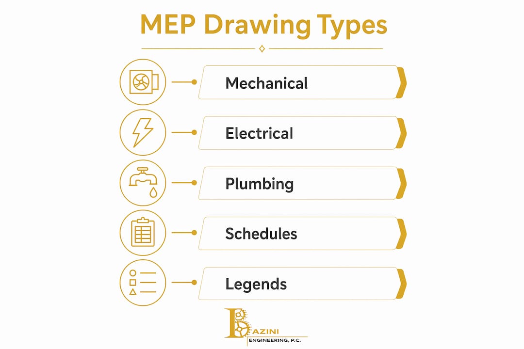
Mechanical drawings
Mechanical drawings cover HVAC systems, including duct routing, equipment locations, riser diagrams, and equipment schedules for items like air handling units and exhaust fans. They show duct sizes, airflow directions, and equipment specifications in enough detail for fabrication and installation.

Electrical drawings
Electrical drawings detail lighting layouts, power distribution, panel schedules, conduit runs, and low-voltage systems. A panel schedule, for example, lists every circuit breaker, its load, and the equipment it serves. This level of detail is critical for electrical subcontractors and for coordination with structural elements like beams and slabs.
Plumbing drawings
Plumbing drawings cover domestic water supply, sanitary drainage, storm drainage, and gas piping. Riser diagrams show the vertical routing of pipes through a building, which is especially important in multi-story projects where pipe sizing and pressure zones must be carefully managed.
Additional drawing types
Beyond the three core disciplines, a complete MEP set typically includes:
- Fire protection drawings showing sprinkler layouts, standpipes, and fire alarm device locations
- Penetration details showing how pipes and ducts pass through rated walls and floors
- Shop drawings submitted by subcontractors for engineer review before fabrication
- Coordination drawings produced during BIM clash detection reviews
Key drawing components
Every MEP drawing set shares common elements that professionals must understand before reading any floor plan:
| Component | Purpose |
|---|---|
| Legend | Defines all symbols and abbreviations used in the drawing set |
| Equipment schedule | Lists model numbers, capacities, electrical requirements, and weights |
| General notes | States design assumptions, code references, and scope boundaries |
| Riser diagram | Shows vertical system routing and connections between floors |
| Detail sheets | Provide large-scale views of complex connections or assemblies |
Equipment schedules list model numbers, capacities, electrical requirements, and weights. These schedules drive procurement decisions and structural coordination for heavy equipment like rooftop units and generators.
How are MEP drawings developed from brief to construction documents?
The standard MEP design workflow follows seven phases, each building on the last to produce a complete, permit-ready drawing set.
-
Project briefing. The engineer meets with the owner and architect to define project scope, occupancy type, and operational requirements. This phase establishes the budget and schedule constraints that shape all design decisions.
-
Basis of Design (BOD) report. The engineer produces a BOD report defining design criteria, applicable codes, and system philosophy. This document becomes the reference point for all subsequent design decisions and energy code compliance verification.
-
Schematic design. Engineers produce preliminary layouts showing system locations and major equipment. These drawings are not construction-ready but confirm that the proposed systems fit within the architectural floor plan.
-
Design development. Engineers refine layouts, complete load calculations, and select equipment. Duct sizes, pipe diameters, and panel capacities are determined at this stage.
-
BIM coordination. The design team assembles a federated BIM model combining architectural, structural, and MEP models. Clash detection tools like Autodesk Revit and Navisworks identify physical conflicts between systems before construction begins.
-
Construction documents (CDs). The final drawing set includes fully annotated floor plans, riser diagrams, equipment schedules, and technical specifications. These documents are submitted for permit review.
-
As-built documentation. After construction, the drawing set is updated to reflect actual installed conditions. As-built drawings are required for building operations, future renovations, and regulatory compliance.
Pro Tip: Request the BOD report at project kickoff. It tells you which codes govern the design, what system types were selected and why, and what assumptions the engineer made. That context makes every subsequent drawing decision easier to evaluate.
How to read MEP drawings effectively on a project
Reading MEP drawings correctly is a skill that separates professionals who catch problems early from those who discover them during construction.
Start with the legend and general notes, not the floor plans. The legend defines every symbol and abbreviation used in that specific drawing set. Project-specific symbols frequently override generic industry standards, so relying on memory or a generic reference guide leads to misreadings.
General notes often contain critical scope information. Phrases like "NIC" (Not In Contract) or "by others" indicate work that is excluded from the contractor's scope. Missing these notes during bidding creates pricing errors and generates RFIs during construction.
Scale verification is equally important. MEP floor plans for large buildings commonly use a scale of 1/8"=1'-0", while equipment rooms use larger detail scales. Always verify scale from the graphic scale bar on each sheet, not from the title block alone. Printed PDFs are frequently scaled differently than the original drawing, which causes installation errors if measurements are taken directly from the sheet.
A complete drawing review covers these document types in sequence:
- General notes and legend
- Floor plans for each discipline
- Riser diagrams for vertical system routing
- Equipment schedules for procurement and structural coordination
- Detail sheets for complex connections and penetrations
Pro Tip: Cross-reference the electrical equipment schedule against the mechanical equipment schedule. Every major HVAC unit has an electrical requirement. If those two schedules do not align, you have a coordination gap that will generate a change order.
How does BIM coordination reduce MEP construction conflicts?
Traditional 2D coordination required engineers and contractors to manually overlay drawings from different disciplines to find conflicts. That process was slow, error-prone, and often incomplete. Physical clashes between ductwork, structural beams, and plumbing pipes were routinely discovered only after installation had begun.
BIM-enabled coordination replaces that manual process with a federated 3D model that combines all disciplines in a single digital environment. Clash detection runs automatically, flagging every point where two systems occupy the same space. Engineers resolve those conflicts in the model before any contractor picks up a tool.
The practical benefits extend beyond clash detection. BIM models allow engineers to verify that required maintenance clearances around equipment are achievable within the actual building geometry. A rooftop unit that looks fine on a 2D plan may have no accessible service path when modeled in three dimensions.
| Coordination method | Conflict detection | Resolution timing | Rework risk |
|---|---|---|---|
| 2D overlay | Manual, incomplete | During construction | High |
| Federated BIM model | Automatic, comprehensive | Before construction | Low |
Early BIM coordination compresses project timelines and reduces change orders. Project teams that prioritize coordination before permit submission see measurable savings compared to those who treat coordination as a construction phase activity.
What practical tips help professionals avoid common MEP drawing mistakes?
The most frequent mistakes on construction projects trace back to incomplete or misread MEP drawings. Knowing where those mistakes happen is the first step to preventing them.
General notes flagging NIC or "by others" are scope gap indicators that subcontractors routinely miss during bidding. Properly identifying these notes saves significant contractor cost and reduces RFI volume during construction.
As-built drawings are another common failure point. Field crews make changes during installation, but those changes do not always make it back into the drawing set. An outdated as-built is worse than no as-built because it creates false confidence. Assign a specific team member to track field changes and update the drawing set in real time.
Cross-disciplinary coordination cannot happen in silos. A plumbing engineer who designs without reviewing the structural drawings may route a drain line directly through a beam. An electrical engineer who does not coordinate with the mechanical team may place a panel in a space that the HVAC engineer has already allocated for ductwork. Regular coordination meetings with all disciplines present prevent these conflicts from reaching the field.
Pro Tip: When reviewing a drawing set for the first time, flag every note that says "coordinate with" or "verify in field." Each one of those notes is a potential RFI waiting to happen. Resolve them before bidding, not during construction.
Key Takeaways
MEP drawings are the single most critical set of documents for coordinating building systems, and reading them correctly from the legend outward prevents the majority of costly field conflicts.
| Point | Details |
|---|---|
| Start with the legend | Always read the project-specific legend before interpreting any floor plan symbol. |
| BOD report sets the foundation | The Basis of Design report defines codes, system types, and design assumptions for the entire project. |
| BIM replaces 2D overlay | Federated BIM models with Revit and Navisworks detect clashes automatically before construction begins. |
| Equipment schedules drive coordination | Cross-referencing mechanical and electrical schedules catches power and structural conflicts early. |
| As-built accuracy is non-negotiable | Updated as-built drawings are required for operations, future renovations, and regulatory compliance. |
What I have learned from years of MEP coordination
The biggest mistake I see project managers and architects make is treating MEP drawings as a contractor problem. They review the architectural drawings carefully, then hand the MEP set to the subcontractors and assume the engineers have handled everything. That assumption is expensive.
MEP drawings require active engagement from every member of the project team. An architect who understands the mechanical riser diagram can catch a conflict with a proposed ceiling height before the drawings go to permit. A project manager who reads the general notes can identify scope gaps before they become change orders. These are not engineering tasks. They are project management tasks that require engineering literacy.
Early BIM coordination is the single highest-return investment a project team can make. I have seen projects where coordination started during design development save weeks of construction time and eliminate dozens of RFIs. I have also seen projects where coordination was skipped to save time, only to spend three times as long resolving field conflicts. The math is not complicated.
My advice to professionals new to MEP drawings is simple. Do not try to read a floor plan first. Read the legend, read the general notes, then read the riser diagrams. By the time you get to the floor plans, you will already understand the system logic. The floor plans will make sense instead of looking like a tangle of lines.
— Joseph
Baziniengineering's MEP engineering services for your project
Baziniengineering produces coordinated, permit-ready MEP construction documents for commercial, residential, institutional, and industrial projects across New York City, Long Island, and Westchester County.

The firm's MEP engineering services cover mechanical, electrical, plumbing, and fire suppression design, with full BIM coordination and energy code compliance built into every project. Baziniengineering works directly with the NYC Department of Buildings and FDNY to support permit expediting and agency approvals. If your project needs coordinated construction documents that hold up through permit review and construction, Baziniengineering has the experience to deliver them.
FAQ
What does MEP stand for in construction drawings?
MEP stands for Mechanical, Electrical, and Plumbing. These three disciplines cover the primary building systems documented in an MEP drawing set, often with fire protection added as a fourth discipline.
How do I start reading an MEP drawing set?
Start with the legend and general notes before reviewing any floor plan. The legend defines project-specific symbols, and the general notes identify scope boundaries and items excluded from the contractor's work.
What is a Basis of Design report in MEP projects?
The Basis of Design (BOD) report is a document produced at the start of design that defines applicable codes, system types, and design criteria. It serves as the reference point for all MEP specifications and energy code compliance verification throughout the project.
How does BIM improve MEP drawing coordination?
BIM tools like Autodesk Revit and Navisworks create a federated 3D model combining all disciplines. Automatic clash detection identifies physical conflicts between systems before construction begins, reducing rework and change orders.
What are equipment schedules in MEP drawings?
Equipment schedules list model numbers, capacities, electrical requirements, and weights for every piece of equipment in the project. They are used for procurement, structural coordination, and verifying that electrical and mechanical designs are aligned.