
Reading mechanical engineering drawings is the process of interpreting graphical and textual information that precisely defines part geometry, manufacturing tolerances, surface finishes, and inspection criteria. Known formally as technical drawing interpretation, this skill separates engineers who produce accurate parts from those who generate expensive scrap. A 3D STEP file conveys geometry but lacks tolerances, surface finish, materials, and manufacturing notes, which only the 2D drawing or PMI provide. Whether you are a student entering your first fabrication project or a licensed professional reviewing shop drawings, mastering this process is non-negotiable.
How to read mechanical engineering drawings: start with the title block
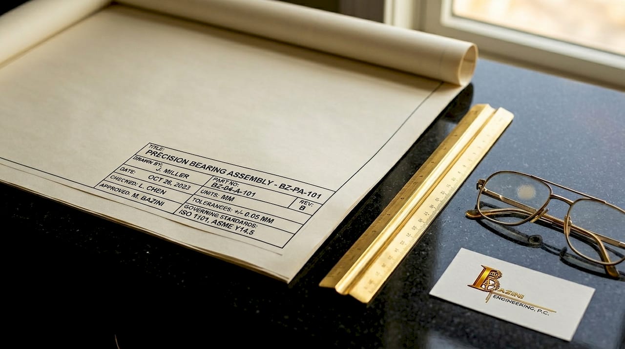
The title block is the single most important starting point on any drawing. Located at the bottom right of the sheet, it contains critical metadata including part identification, revision level, scale, units, material specification, and the governing standard such as ASME Y14.5-2018 or ISO GPS. Reading this block before anything else sets the interpretive rules for every dimension, tolerance, and symbol on the sheet.
The title block also tells you which unit system applies. Mixing up millimeters and inches is not a minor error. Converting 0.1 mm to inches incorrectly or missing a drawing revision causes scrap or rework, both of which are entirely avoidable with a disciplined first step.
Revision control deserves its own moment of attention. Drawings go through multiple revisions as designs evolve, and manufacturing from an outdated revision produces incorrect parts. Always confirm the revision letter or number on your drawing matches the latest issued revision before you proceed.
Here is what to verify in the title block before moving forward:
- Part number and name: Confirm you have the correct drawing for the component in question.
- Revision level: Match it against the latest revision in the document control system.
- Units: Identify whether dimensions are in inches or millimeters.
- Scale: Understand the ratio so you do not scale dimensions from the printed sheet.
- Governing standard: Note whether ASME Y14.5, ISO 1101, or another standard applies, since interpretation rules differ.
- Material and finish: These may appear here or in a separate notes block.
Pro Tip: The governing standard cited in the title block dictates how every GD&T symbol and tolerance is interpreted. Identify it before reading a single dimension, or you risk applying the wrong rules to the entire drawing.
What are the different view types and projection methods?
Mechanical drawings represent a three-dimensional part using multiple two-dimensional views. Understanding how those views are arranged is critical before you trust any dimension.
The four most common view types are:
- Orthographic views: Front, top, and right-side views that show the part from perpendicular angles. These carry the majority of dimensional information.
- Section views: Cut through the part along a defined plane to reveal internal geometry, such as bores, counterbores, or wall thicknesses that are hidden in standard views.
- Detail views: Enlarged portions of a drawing, labeled with a circle and letter, used when features are too small to dimension clearly at the drawing scale.
- Isometric views: Three-dimensional pictorial representations included for reference only. Never dimension from an isometric view.
Projection method is where many readers make their first serious mistake. Third-angle projection is standard in the US and Canada, while first-angle projection is used in Europe and much of Asia. In third-angle, the top view appears above the front view. In first-angle, it appears below. Misreading the projection system can produce a mirrored or flipped part with no obvious visual warning.
Projection symbols are mandatory for clarity. Verifying the projection system before trusting dimensions prevents costly mirrored or flipped parts that pass visual inspection but fail assembly.
The projection symbol, a small standardized icon near the title block, tells you which system applies. After identifying it, do a quick sanity check: confirm that the view layout on the sheet matches the expected arrangement for that projection type. This takes thirty seconds and eliminates one of the most common sources of manufacturing error.
How do dimensions and tolerances control part acceptability?
Every dimension on a mechanical drawing carries two pieces of information: the nominal value and the allowable variation. The nominal value is the target size. The tolerance defines how far from that target the manufactured part can deviate and still be accepted.
When no explicit tolerance appears next to a dimension, the default tolerance block governs the acceptable range. This block, typically labeled "Unless Otherwise Specified," sets general tolerances for linear dimensions, angular dimensions, and sometimes surface finish. Missing this block is a beginner error with real consequences.
| Tolerance format | Example | When it applies |
|---|---|---|
| Bilateral tolerance | 25.00 ± 0.05 | Equal variation allowed in both directions |
| Limit dimensions | 24.95 / 25.05 | Explicit upper and lower bounds stated |
| Default tolerance block | ±0.1 mm (per block) | Applied when no individual tolerance is shown |
| Reference dimension | (25.00) | For information only; not inspected or controlled |
Tighter tolerances cost more to manufacture. A tolerance of ±0.001 inch requires precision grinding or honing, while ±0.010 inch is achievable with standard CNC milling. When you read a drawing for quoting or inspection, identify which dimensions carry the tightest tolerances first. Those features drive process selection, fixturing requirements, and inspection time.
Note that explicit GD&T callouts or notes can override default tolerances on specific features. A dimension may fall under the default tolerance block, but if a feature control frame references that same feature, the GD&T requirement takes precedence.
Pro Tip: Reference dimensions, shown in parentheses, are never inspected. They exist to help the reader understand the drawing, not to control the part. Do not apply a tolerance to them or flag them during inspection.
How do you interpret GD&T feature control frames and surface finish symbols?
Geometric Dimensioning and Tolerancing, or GD&T, is the standardized language for controlling the shape, orientation, location, and runout of features beyond simple size tolerances. The feature control frame is its primary vehicle.
Feature control frames are read left to right and encode four elements: the geometric characteristic symbol, the tolerance value and zone shape, any material condition modifiers, and the datum references. A position callout reading ⌖ | ⌀ 0.010 Ⓜ | A | B | C means the feature must fall within a cylindrical tolerance zone of 0.010 inch diameter at Maximum Material Condition, referenced to datums A, B, and C in that order.
Common GD&T symbols you will encounter on most mechanical drawings include:
- Position (⌖): Controls the location of a feature relative to datums. The most frequently used GD&T callout in manufacturing.
- Flatness (⏥): Controls the variation of a surface within a parallel-plane zone. No datum reference required.
- Perpendicularity (⊥): Controls the angular relationship of a surface or axis to a datum, within a specified tolerance zone.
- Circularity (○): Controls the roundness of a cross-section independent of the axis.
- Cylindricity (⌭): Controls the combined form of a cylinder including circularity, straightness, and taper.
Material condition modifiers change the tolerance zone size based on the actual produced size of the feature. Maximum Material Condition (MMC) allows the tolerance zone to increase as the feature departs from its maximum material size, which is a bonus tolerance that reduces manufacturing cost. Least Material Condition (LMC) works in the opposite direction. Regardless of Feature Size (RFS) applies the stated tolerance regardless of actual size and is the default when no modifier appears.
Datum order matters more than most readers realize. The primary datum constrains the most degrees of freedom, directly impacting how a part is fixtured during machining and inspection. A part measured against datum A first will yield different results than one measured against datum B first if the surfaces are not perfectly square to each other.
Surface finish symbols appear as a checkmark-like icon with an Ra value. Ra 3.2 µm is a standard machined finish, while Ra 0.8 µm indicates a precision finish required for bearing surfaces or sealing faces. Lower Ra values mean finer finishes, longer machining time, and higher cost. When you see a surface finish callout, connect it immediately to the functional requirement of that surface.
What notes and flags do you check before finalizing your interpretation?
Notes and flag callouts carry manufacturing instructions that cannot be expressed through dimensions or GD&T alone. Ignoring notes is a common cause of errors in fabrication and inspection, particularly for processes like deburring, heat treatment, anodizing, or torque requirements.
General notes appear in a block, usually in the upper left or lower left of the drawing sheet. Flag notes are numbered callouts tied to specific features on the drawing face. Both carry mandatory requirements unless explicitly marked as reference information.
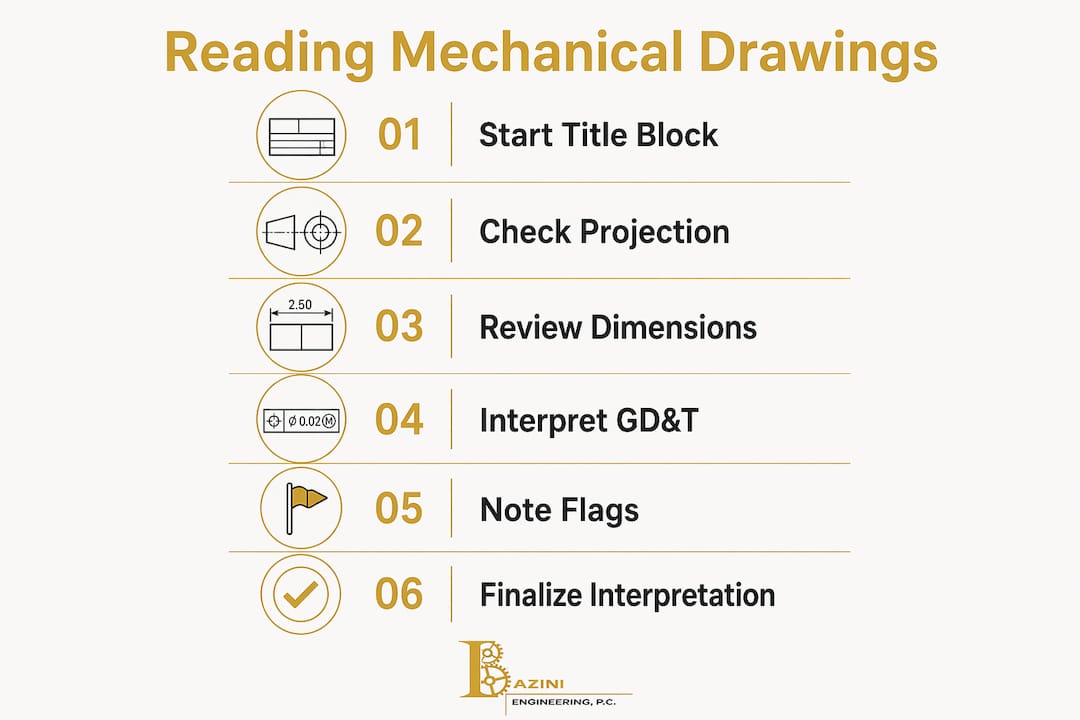
Follow this sequence every time you interpret a drawing for manufacturing or inspection:
- Read the title block and confirm revision, units, and governing standard.
- Identify the projection method and verify view layout.
- Locate and read the default tolerance block.
- Scan all views and identify the primary geometry and critical features.
- Read all dimensions and note which carry explicit tolerances vs. default tolerances.
- Interpret all GD&T feature control frames and identify datum references.
- Read all general notes and flag notes in full.
- Flag any ambiguities and contact the responsible engineer before proceeding.
A stepwise approach catches common errors and reduces nonconforming parts. The most expensive mistake in manufacturing is building the wrong part with confidence. When a drawing is unclear or contradictory, the correct response is always to ask, not to assume.
Pro Tip: When quoting a job from a drawing, read the notes last but price them first. Heat treatment, special coatings, and tight surface finish requirements often represent the majority of the part cost.
Key takeaways
Reading mechanical engineering drawings accurately requires a fixed sequence: title block first, projection method second, tolerances and GD&T third, and notes last, with every step verified before manufacturing begins.
| Point | Details |
|---|---|
| Start with the title block | Confirm revision, units, governing standard, and material before reading any dimension. |
| Verify the projection method | Identify first-angle or third-angle projection to avoid mirrored or flipped part errors. |
| Understand tolerance hierarchy | Default tolerance blocks apply broadly; explicit GD&T callouts override them on specific features. |
| Read GD&T left to right | Feature control frames encode characteristic, tolerance zone, modifiers, and datums in sequence. |
| Never skip the notes | General and flag notes carry mandatory manufacturing instructions not captured in dimensions. |
Why drawings are a language, not a picture
After years of reviewing mechanical design documentation across commercial and industrial projects, the most consistent mistake I see from both students and experienced professionals is treating a drawing like a picture to be visually scanned rather than a language to be read systematically.
Drawings are a precise language. Every line weight, every symbol, and every note placement follows rules defined by ASME Y14.5 or ISO GPS. When you skip the title block or assume the projection method without checking, you are reading without knowing the grammar. The result is predictable.
My strongest recommendation is to build a repeatable workflow and use it without exception, even on drawings that look simple. The drawings that cause the most expensive errors are rarely the complex ones. They are the straightforward drawings where a reader assumed they already understood the context and skipped a step.
Stay curious about the standards. ASME Y14.5-2018 is not light reading, but understanding even its foundational sections on datums and material condition modifiers will change how you read every drawing you encounter. The professionals who read technical drawings with genuine confidence are not the ones with the most experience. They are the ones who learned the rules deeply and apply them consistently.
— Joseph
Work with engineers who speak the language fluently

Baziniengineering brings over a decade of professional engineering experience to every project, including mechanical, electrical, plumbing, and fire protection design for commercial, residential, and industrial clients across New York and Florida. When drawing interpretation questions arise on complex projects, or when your team needs code-compliant MEP engineering documentation that is clear and buildable, Baziniengineering delivers. Visit Bazini Engineering, PC to learn more about our engineering services and to request a consultation for your next project.
FAQ
What is the first step to read a mechanical drawing?
Start with the title block at the bottom right of the sheet. It confirms the part number, revision level, units, scale, material, and governing standard before you interpret any dimension or symbol.
What is the difference between first-angle and third-angle projection?
Third-angle projection is standard in the US and Canada, placing the top view above the front view. First-angle projection, used in Europe and Asia, places the top view below the front view. A standardized symbol near the title block identifies which system applies.
What does a GD&T feature control frame tell you?
A feature control frame specifies the geometric characteristic being controlled, the tolerance zone size and shape, any material condition modifiers such as MMC or LMC, and the datum references used for measurement and fixturing.
Why do notes matter when interpreting engineering schematics?
Notes carry mandatory manufacturing instructions for processes like deburring, heat treatment, and surface coatings that cannot be expressed through dimensions alone. Skipping notes is one of the most common causes of nonconforming parts.
When does a default tolerance block apply?
The default tolerance block applies to any dimension on the drawing that does not carry its own explicit tolerance. It is typically labeled "Unless Otherwise Specified" and sets the acceptable variation for linear and angular dimensions across the entire drawing.