
Reading fire protection engineering plans is the process of systematically interpreting specialized construction drawings that detail fire suppression, alarm, and life safety systems to verify code compliance and coordinate installations. These documents, formally called fire protection design documents or fire protection shop drawings, govern everything from sprinkler head placement to hydraulic pressure margins. For project managers, contractors, and code enforcement officers working under 2026 International Building Code requirements, the ability to analyze these plans accurately is not optional. Errors in interpretation cause permit rejections, installation conflicts, and in the worst cases, life safety failures.
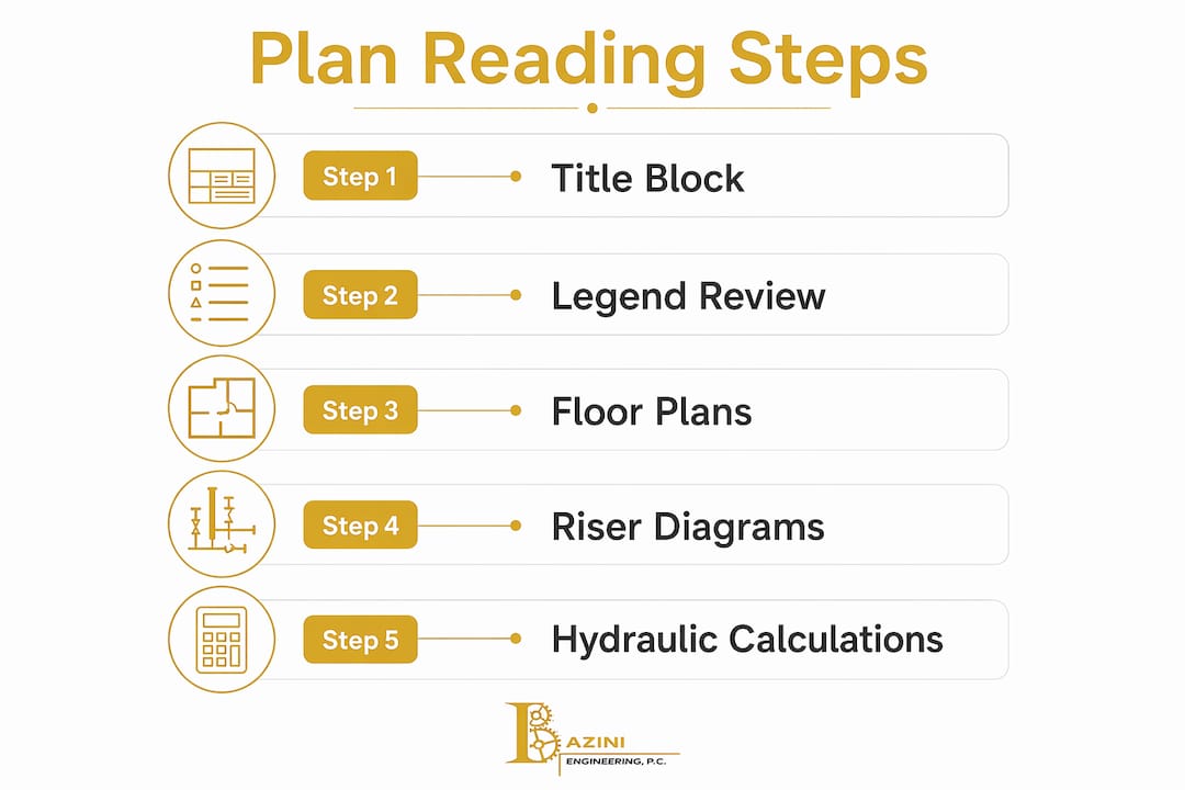
How to read fire protection engineering plans: starting with the title block and legend
Every fire protection plan review starts at the title block, located in the lower right corner of each drawing sheet. The title block contains the project name, address, drawing date, revision history, designer credentials, and the scale used for the drawing. These details are not administrative formalities. The revision date tells you whether you are working from a current set, and the scale determines whether your field measurements will match the design intent.

After the title block, move directly to the drawing legend. The legend defines every symbol used on that specific project, and symbol meanings vary by jurisdiction, which means assuming you know what a symbol means without checking the legend is a reliable path to misinterpretation. Cross-reference the project legend against NFPA 170, the standard for fire safety and emergency symbols, but always treat the project legend as the controlling document for that set.
Common symbols you will encounter include:
- Sprinkler heads: Shown as circles, crosses, or triangles depending on type (pendant, upright, sidewall)
- Control valves: Typically depicted as a butterfly or gate valve symbol with a tag number
- Alarm initiation devices: Pull stations, smoke detectors, and heat detectors each carry distinct symbols
- Piping: Solid lines for wet systems, dashed lines for dry or pre-action branches, with pipe size labeled at intervals
- Riser diagrams: Schematic views showing vertical pipe routing, floor connections, and valve locations
Fire protection drawing sets typically include floor plan sheets, riser diagrams, hydraulic calculation reference sheets, and detail sheets for specialty components. Tools like AutoCAD and Bluebeam Revu are standard for digital review, and Bluebeam's markup tools allow you to trace pipe runs and flag coordination conflicts directly on the PDF.
Pro Tip: When reviewing a multi-sheet set, print or pin the legend sheet alongside each floor plan. Toggling between sheets wastes time and increases the chance of symbol misidentification.
How do occupancy classifications affect fire system requirements?
IBC occupancy classification governs construction type, fire separation distances, sprinkler system selection, and alarm requirements. This makes occupancy the single most consequential data point on any fire protection plan. A Group A-2 assembly occupancy (restaurant) triggers different sprinkler density requirements than a Group S-1 storage occupancy, even if the two buildings are identical in size and construction.
The following table shows how occupancy classification maps to key fire protection requirements under the 2026 IBC and NFPA 13:
| Occupancy group | Sprinkler requirement | Fire separation | Hazard classification |
|---|---|---|---|
| A (Assembly) | Required above 300 occupants or 12,000 sq ft | 2-hour rated walls typical | Ordinary Hazard Group 1 |
| B (Business) | Required in high-rise or per local code | 1-hour rated partitions | Light Hazard |
| S-1 (Storage) | Required in most configurations | 2-hour rated walls | Ordinary or Extra Hazard |
| I (Institutional) | Required throughout | 2-hour rated construction | Light to Ordinary Hazard |
On the drawings themselves, fire-rated walls appear as bold or double lines, often with a label such as "2HR" or "FR" adjacent to the wall. Floor assemblies with fire ratings are noted in section details or on a separate life safety plan sheet. Life safety plans consolidate fire-rated construction, egress routes, alarm device placement, and sprinkler coverage in a single reference drawing, making them the fastest way to verify compartmentalization compliance during a plan review.
When you identify a fire-rated assembly on the drawings, verify that the rating matches the occupancy separation requirement for the adjacent spaces. A common oversight is accepting a 1-hour rated wall between a Group B and Group S-1 occupancy when the code requires 2 hours. That discrepancy will surface during inspection, not during permit review, which makes it far more expensive to correct.
How to trace sprinkler systems, control valves, and alarm devices
Tracing a sprinkler system from source to endpoint is the most reliable method for confirming design completeness. Follow this sequence on every set of fire protection blueprints you review:
- Locate the water supply connection. Find the point where the underground main connects to the building's fire service entrance. The riser diagram shows this connection, including the backflow preventer, main drain, and system riser valve.
- Identify the system type. Wet pipe systems show solid lines throughout. Dry pipe systems label the dry pipe valve location and show the air supply connection. Pre-action systems include a pre-action panel symbol and solenoid valve notation.
- Trace the main to branch lines. Follow the main feed pipe from the riser to each branch line. Pipe sizes are labeled at each reduction point. Confirm that pipe sizing is consistent with the hydraulic calculation reference nodes shown on the plan.
- Locate all control valves. Every control valve must be tagged with an identification number that matches the valve schedule. Supervisory switches on control valves connect to the fire alarm system, so verify that each valve tag appears on both the sprinkler drawings and the fire alarm drawings.
- Map alarm initiation and notification devices. On the fire alarm floor plans, locate pull stations at exits, smoke detectors in corridors and mechanical rooms, and heat detectors in kitchens or high-temperature spaces. Notification appliances (horns, strobes) must meet NFPA 72 spacing and candela requirements.
- Check for MEP coordination conflicts. Overlay the sprinkler floor plan against the HVAC ductwork and electrical conduit drawings. Conflicts between sprinkler branch lines and large duct runs are among the most common causes of field change orders.
Pro Tip: On complex projects, use Bluebeam Revu's overlay pages feature to stack the sprinkler plan directly over the HVAC plan. Conflicts appear immediately without manual comparison.
What supporting documents complete a fire protection submittal?
Fire protection design documents do not stand alone. A complete submittal package for municipal permit review includes hydraulic calculation reports, stamped shop drawings, product data sheets, and a water flow test report. Omitting water flow test data or seismic bracing documentation causes project delays and OSHA citations that can reach $16,131 per violation. That figure represents a single line item in a submittal checklist that takes less than an hour to verify.
Hydraulic calculations are the mathematical proof that the sprinkler system delivers the required water density at the most hydraulically remote area. Reviewers check design density, friction loss, and supply margins to confirm the system performs under worst-case conditions. The calculation report references specific node IDs that must appear on the corresponding floor plan sheets. A mismatch between node IDs in the calculations and the plan labels is one of the most common causes of immediate submittal rejection.
The following comparison shows what a complete versus incomplete submittal typically contains:
| Document | Complete submittal | Incomplete submittal |
|---|---|---|
| Shop drawings | Stamped, signed, current revision | Unsigned or outdated revision |
| Hydraulic calculations | Node IDs match plan labels | Node IDs inconsistent with drawings |
| Product data sheets | All listed components covered | Missing sprinkler head or valve data |
| Water flow test report | Current (within 12 months) | Absent or expired |
| Seismic bracing details | Included per NFPA 13 requirements | Omitted entirely |
Coordinating the fire protection submittal with the life safety drawings and fire alarm drawings before submission catches the majority of cross-discipline errors. Standardized BIM workflows and quality assurance checks reduce costly review cycles by aligning drawings with design intent before the package reaches the authority having jurisdiction (AHJ).
Common mistakes when reading fire safety diagrams
Even experienced reviewers make predictable errors when analyzing fire protection plans. Recognizing these patterns reduces the chance of a costly revision cycle.
- Ignoring local legend variations. NFPA 170 provides baseline symbols, but jurisdictions and individual designers add custom symbols. Always read the project legend before interpreting any symbol on the drawing.
- Skipping the riser diagram. Floor plans show horizontal distribution, but the riser diagram reveals vertical pipe routing, system zoning, and valve locations that do not appear on any floor plan sheet.
- Failing to cross-check hydraulic nodes. Every node ID in the hydraulic calculation report must appear on the shop drawings. Missing or mismatched nodes cause immediate rejection by plan reviewers.
- Overlooking fire-rated assembly conflicts. A wall shown as fire-rated on the life safety plan must match the construction type shown on the architectural drawings. Discrepancies between disciplines are a primary cause of field non-compliance.
- Missing mandatory submittal components. Using outdated or incomplete drawings is a primary cause of plan rejection and creates safety risks that persist through the building's operational life.
- Not coordinating with MEP drawings. Sprinkler branch lines routed through spaces without checking HVAC, electrical, or plumbing layouts generate field conflicts that delay installation and increase project costs.
Before submitting any package, run a structured internal review against a checklist that covers every item the AHJ will examine. Communication with the designer before submission, rather than after rejection, is the most efficient use of everyone's time.
Key takeaways
Reading fire protection engineering plans requires systematic verification of the title block, legend, occupancy classification, hydraulic calculations, and supporting documents before any field or permit work proceeds.
| Point | Details |
|---|---|
| Start with title block and legend | Verify drawing revision date and cross-reference all symbols against the project-specific legend. |
| Occupancy drives system requirements | IBC occupancy classification determines sprinkler type, fire separation ratings, and alarm design. |
| Trace systems from source to endpoint | Follow water supply from the riser through branch lines to confirm pipe sizing and valve tagging. |
| Hydraulic nodes must match plan labels | Node ID mismatches between calculations and drawings cause immediate submittal rejection. |
| Supporting documents complete the package | Stamped shop drawings, flow test reports, and product data sheets are all required for permit approval. |
Why plan accuracy matters more than most professionals realize
After working on fire protection projects across New York City and Long Island, I have seen one pattern repeat itself more than any other: professionals treat fire protection drawings as static documents. They review them once at permit submission, file them away, and assume the approved set reflects what was built. It rarely does.
Fire alarm system drawings evolve from design through installation to as-built documents, and failure to maintain current as-built drawings creates inaccuracies that directly hamper maintenance and inspections. I have walked buildings where the installed sprinkler layout bore little resemblance to the permitted drawings because field changes were never documented. That gap is not just a paperwork problem. It is a liability that surfaces during the next inspection or, worse, during an actual fire event.
The 2026 code cycle has tightened requirements around documentation maintenance. Operational fire safety plans must be updated annually and communicated to staff within 90 days of any change. That standard applies to the operational side, but the engineering drawings that underpin those plans carry the same obligation. If you are a contractor or project manager, build as-built drawing updates into your project closeout checklist as a non-negotiable deliverable, not an afterthought.
The professionals who read fire protection plans most effectively are not necessarily the ones with the most technical knowledge. They are the ones who treat every drawing set as a hypothesis to be verified against the actual building, the calculations, and the code. That mindset is what separates a plan review that catches problems from one that simply processes paperwork.
— Joseph
How Baziniengineering supports your fire protection plan review

Baziniengineering provides fire protection engineering design and plan review services for commercial, residential, and institutional projects across New York City, Long Island, and Westchester County. The firm's MEP/FP team produces permit-ready fire protection design documents coordinated with architectural, structural, and MEP drawings, reducing AHJ rejection cycles and keeping projects on schedule. With direct experience coordinating submissions with the NYC Department of Buildings and FDNY, Baziniengineering delivers code-compliant designs aligned with 2026 IBC and NFPA standards. Whether you need a full sprinkler system design, hydraulic calculations, or submittal support, the team at Baziniengineering is equipped to move your project forward.
FAQ
What is the first step to read fire protection engineering plans?
Start with the title block to confirm the drawing revision date and designer credentials, then review the drawing legend before interpreting any symbol. These two steps prevent the most common misreading errors.
How do occupancy classifications appear on fire protection drawings?
Occupancy classifications are typically noted in the title block, on the life safety plan sheet, or in a general notes section. They determine sprinkler system type, fire separation ratings, and alarm design requirements under the 2026 IBC.
Why do hydraulic calculation node IDs matter during plan review?
Every node ID in the hydraulic calculation report must be explicitly identified on the corresponding shop drawings. Inconsistencies between node IDs and plan labels are a leading cause of immediate submittal rejection by plan reviewers.
What documents must accompany fire protection shop drawings for permit submission?
A complete submittal includes stamped shop drawings, hydraulic calculation reports, product data sheets for all listed components, a current water flow test report, and seismic bracing details per NFPA 13. Missing any of these components delays permit approval.
How often should fire protection drawings be updated?
Fire protection drawings are living documents that require updates whenever system changes, renovations, or equipment replacements occur. Outdated as-built drawings are a primary cause of plan rejection and create safety risks during inspections and maintenance.