

TL;DR:
- As-built MEP drawings record the exact installed systems in a building and are essential for future renovation and maintenance. They should be prepared using specified standards like LOD 300, capture data at key milestones with laser scanning, and be coordinated across disciplines to avoid costly errors. Properly delivered, these digital assets support permits, renovations, and long-term facility management effectively.
As-built MEP drawings are post-construction documents that record the exact installed locations, sizes, and routing of mechanical, electrical, and plumbing systems in a completed building. Every construction professional who needs to prepare as-built MEP drawings is creating a legal and operational record that governs future renovations, permit applications, and facility maintenance. These drawings differ from design-intent documents because they reflect what was actually built, not what was originally planned. Standards like LOD 300 and tools like laser scanning have made this process more reliable and auditable than ever before.
What prerequisites and tools do you need to prepare as-built MEP drawings?
Preparation starts before a single measurement is taken. The first decision is defining the Level of Development. LOD 300 is the most commonly requested standard for MEP renovation design and coordination because it specifies precise dimensions, routing, and system relationships. Setting LOD at project kickoff aligns expectations between the owner, engineer, and contractor before any field work begins.

You also need to gather the right project inputs. Budget estimates and scope definitions rely on the building address, approximate square footage, and the specific drawing types required. A full MEP set costs more than floor plans alone, and square footage is the primary cost driver. Knowing this upfront prevents scope creep and budget surprises.
The contract language matters as much as the technical inputs. Specify digital as-built documentation and the use of laser scanning technology in the contract before work begins. Vague contract language is one of the most common reasons critical site data goes uncaptured.
Required inputs before starting:
- Building address and square footage
- Existing design and construction documents
- Defined LOD (LOD 300 for most renovation projects)
- Contract language specifying as-built deliverables and formats
- Access to redline markups from the field team
Technology tools for reality capture and modeling:
| Tool Category | Purpose | Output |
|---|---|---|
| Laser scanner (LiDAR) | Captures millimeter-level spatial data | Point cloud data set |
| Total station surveying | Verifies key control points | Coordinate data |
| CAD software (2D) | Produces final drawing sheets | DWG/PDF files |
| BIM platform (3D) | Models MEP systems in 3D space | Coordinated BIM model |
Pro Tip: Confirm that your contract explicitly names the deliverable formats, such as DWG, PDF, and point cloud files, before mobilizing. Missing this step is the single fastest way to lose data at project closeout.
How do you capture and document accurate as-built MEP conditions?
Accurate MEP as-built documentation follows a defined sequence. Skipping or reordering steps produces drawings that fail quality checks and require costly rework.
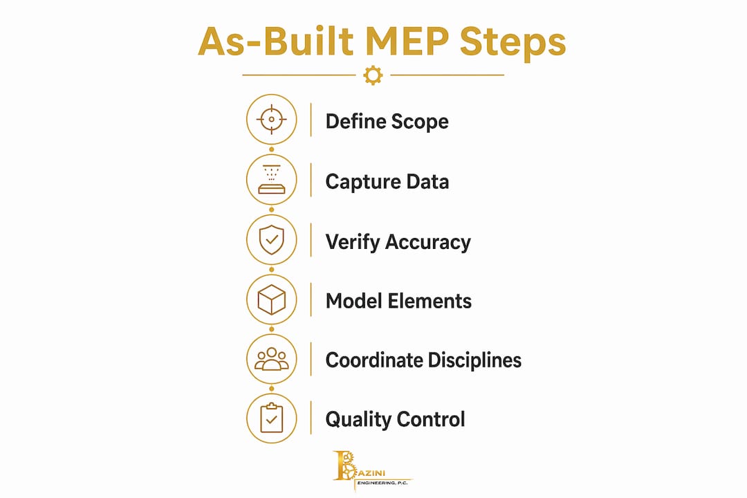
Step 1: Define scope and establish LOD
Confirm the project scope in writing. Identify which MEP disciplines are included, what drawing sheets are required, and what LOD applies to each system. This document becomes the quality benchmark for every step that follows.
Step 2: Capture reality at the right milestones
Optimal timing for MEP field capture is at construction milestones like "in-wall" or "pre-pour," before systems are concealed behind finishes or concrete. Missing these windows means the data is gone. Laser scanning at these stages achieves millimeter-level accuracy that no tape measure or redline can replicate.
Step 3: Verify captured data against design documents
Compare the point cloud or survey data against the original design drawings. Flag every deviation, whether a duct runs 6 inches off its designed centerline or a pipe penetrates a wall at a different elevation. These deviations are the core content of the as-built drawing set.
Step 4: Model MEP elements in CAD or BIM
Build the as-built model to the specified LOD. In a BIM environment, model each mechanical, electrical, and plumbing element as a discrete object with accurate geometry and system properties. In a 2D CAD environment, redraw each system layer by layer using the verified field data as the source, not the original design drawings.
Step 5: Coordinate all MEP disciplines in a unified model
Treating MEP disciplines as an integrated system rather than isolated drawing sets prevents coordination failures. Run clash detection between mechanical, electrical, and plumbing layers. A duct that conflicts with a conduit run in the as-built model signals a real condition in the field that needs resolution before the drawings are finalized.
Step 6: Conduct quality control
Perform spot checks by returning to the field and comparing physical conditions to the model. Cross-validate dimensions against the point cloud. Review every drawing sheet against the project-specific legend and drawing conventions.
Pro Tip: Never use the original design drawings as the base for as-built modeling. Start from the reality capture data and treat the design drawings as a reference only. This single discipline prevents the most common as-built errors.
What are the most common mistakes when creating as-built MEP drawings?
The most damaging mistake is late-stage data capture. Delayed or missing documentation results in costly exploratory demolition when future teams need to locate concealed systems. Once walls are closed and slabs are poured, the only way to recover that data is to open them up again.
The second most common error is treating redline markups as the authoritative source. Redlines should be supplementary notes only. Field markups are made under time pressure, often by multiple people with inconsistent notation. Laser scanning data must be the primary reference.
Drawing convention errors cause a separate category of problems. The project-specific legend sheet is the authoritative source for symbols and notation. Generic online symbol libraries and standard CAD symbol sets are secondary. When a drafter substitutes a generic symbol for the one defined in the project legend, the drawing becomes ambiguous to anyone reading it for permit review or renovation planning.
"Incorporating as-built documentation requirements into initial contracts safeguards critical site data and improves project outcomes." This principle applies directly to MEP projects where concealed systems represent the highest documentation risk.
Common mistakes and how to avoid them:
- Late capture: Schedule laser scanning at in-wall and pre-pour milestones, not at project closeout.
- Redline reliance: Use field markups as supplementary notes, never as the primary data source.
- Symbol errors: Follow the project legend exclusively. Do not substitute generic CAD symbols.
- Isolated discipline modeling: Always coordinate mechanical, electrical, and plumbing in a single model or overlay.
- Vague contracts: Specify deliverable formats, LOD, and capture technology in the contract before work starts.
Inaccurate or uncoordinated MEP drawings are a leading cause of project delays and cost overruns during renovation permitting. Coordination at the documentation stage costs far less than rework in the field.
How do you finalize and deliver as-built MEP drawings?
Final quality assurance requires one more comparison between the completed drawings and the point cloud data. Every dimension, elevation, and routing path gets verified against the scan before the drawing set is released. This step catches errors that slip through earlier reviews.
The standard deliverable package for most commercial projects includes three components:
| Deliverable | Format | Purpose |
|---|---|---|
| 2D CAD drawing set | DWG and PDF | Permit submissions, contractor reference |
| Coordinated BIM model | RVT or IFC | Renovation coordination, clash detection |
| Point cloud data set | RCP or E57 | Future re-measurement, record keeping |
Delivering the point cloud data alongside the 2D CAD drawings creates a permanent digital record. Future teams can extract new measurements from the point cloud without returning to the site. This eliminates re-mobilization costs for any future renovation or addition.
The drawing handoff package should also include a metadata sheet listing the capture date, equipment used, coordinate system, and the name of the engineer of record. This information is required by many local building departments and is standard practice for NYC Department of Buildings submissions.
As-built drawings serve three active functions after delivery. They support permit applications by demonstrating existing conditions to the reviewing authority. They guide renovation contractors who need to know exactly where existing systems run before cutting or connecting. They also feed facility management teams who use them for preventive maintenance scheduling and system upgrades.
Pro Tip: Archive the point cloud data in a location accessible to the facility management team, not just the project file. When a building owner needs to add a new HVAC zone five years from now, that scan is worth more than any drawing.
Key takeaways
Accurate as-built MEP documentation requires early contract specification, reality capture at construction milestones, coordinated modeling to LOD 300, and delivery of both 2D drawings and point cloud data for long-term facility use.
| Point | Details |
|---|---|
| Set LOD at project start | Define LOD 300 before field work begins to align all stakeholders on accuracy requirements. |
| Capture at milestones | Scan at in-wall and pre-pour stages before systems are concealed to avoid data loss. |
| Treat redlines as secondary | Use laser scan data as the primary source; redline markups are supplementary reference only. |
| Coordinate all MEP disciplines | Model mechanical, electrical, and plumbing together to detect clashes before finalizing drawings. |
| Deliver point cloud with drawings | Include the point cloud data set in the handoff package to enable future re-measurement without re-scanning. |
The case for treating as-built documentation as a living asset
Most project teams treat as-built drawings as a closeout formality. That is the wrong frame. After 15 years of working on MEP projects across New York City, I have seen the same pattern repeat: a building owner needs to renovate a floor, the as-built drawings are missing or inaccurate, and the first two weeks of the project are spent doing exploratory demolition to find out where the pipes actually run. That is not a documentation problem. That is a planning failure that was locked in at the contract stage.
The teams that get this right do two things differently. First, they write the as-built scope into the contract before construction starts, with specific LOD requirements and deliverable formats named. Second, they scan at the right milestones, not at the end. An in-wall scan takes a few hours. Cutting open a finished wall to find a mislocated conduit takes days and costs real money.
The point cloud is the part most teams undervalue. A well-organized point cloud delivered with the drawing set means the building owner never has to re-mobilize a survey crew for a future project. That data is a permanent asset. Treat it like one.
— Joseph
Baziniengineering's MEP documentation services
Baziniengineering has delivered code-compliant MEP engineering and as-built documentation for commercial, residential, and institutional projects across New York City, Long Island, and Westchester County since 2010.

The firm's MEP engineering services cover mechanical systems, plumbing, fire suppression, and electrical coordination, with direct experience supporting NYC Department of Buildings submissions and FDNY compliance. Whether you need a full coordinated as-built drawing set for a renovation permit or plumbing system documentation for a new build, Baziniengineering delivers drawings that meet local code requirements and hold up under agency review. Contact the team to discuss your project scope and documentation requirements.
FAQ
What is the standard LOD for MEP as-built drawings?
LOD 300 is the most commonly requested standard for MEP as-built drawings used in renovation design and coordination. It specifies precise dimensions, routing, and system relationships for all mechanical, electrical, and plumbing elements.
Why are redline markups not enough for as-built documentation?
Redline markups are made under time pressure and often contain inconsistencies between contributors. Laser scanning data must serve as the primary source, with redlines used only as supplementary reference.
When is the best time to capture MEP field data?
The best time to capture MEP conditions is at construction milestones like "in-wall" or "pre-pour," before systems are concealed. Missing these windows results in data loss that can only be recovered through costly exploratory demolition.
What formats should an as-built MEP drawing package include?
A complete package includes 2D CAD drawings in DWG and PDF formats, a coordinated BIM model in RVT or IFC format, and the point cloud data set in RCP or E57 format for future re-measurement.
How do as-built MEP drawings support permit applications?
As-built drawings demonstrate existing conditions to the reviewing authority, which is required for renovation permits. Accurate, coordinated drawings reduce review cycles and improve approval timelines with agencies like the NYC Department of Buildings.