
TL;DR:
- Reading HVAC duct layout drawings accurately prevents costly mistakes and ensures system performance.
- Following a systematic five-step approach helps verify equipment, routing, sizes, airflow, and terminals before installation.
HVAC duct layout drawings are the technical documents that define how conditioned air moves through a building, from the air handling unit to every supply and return terminal. Professionals who can accurately interpret HVAC duct layout drawings avoid costly field conflicts, code violations, and system performance failures before a single piece of ductwork gets hung. The industry standard for reading these drawings follows a systematic 5-step approach: identify equipment, trace routing, verify sizes, locate air terminals, and check airflow direction. Mastering this process is the difference between a system that performs on day one and one that requires expensive rework.
How to interpret HVAC duct layout drawings: symbols and components
Every HVAC duct drawing uses a standardized visual language. Reading ductwork blueprints starts with knowing what each line type and symbol represents before you trace a single run.
Line types are the foundation of HVAC schematic interpretation:
- Solid double lines represent supply air ducts carrying conditioned air from the air handling unit (AHU) to the space.
- Dashed lines represent return air ducts pulling air back to the unit.
- Dot-dash lines represent exhaust ducts removing air from the building.
- Labels like "600 x 300 SA" appear alongside duct runs to indicate duct dimensions and airflow type.
Equipment tags identify major mechanical components. AHU stands for air handling unit, FCU for fan coil unit. Each piece of equipment appears as a labeled rectangle or symbol tied to a schedule elsewhere in the drawing set. Grilles, diffusers, and dampers each carry their own symbol, typically a circle or rectangle with a tag referencing a separate equipment schedule.
Airflow direction arrows show which way air moves through each duct segment. These arrows are not decorative. Missing or misreading them causes installers to connect branches in reverse, which pressurizes spaces incorrectly and creates comfort complaints.
Pro Tip: Always locate the drawing legend before reading any other part of the sheet. Different engineers use slightly different symbol conventions, and the legend is the only authoritative reference for that specific set of drawings.
How do you read and verify duct sizes and airflow data?
Duct size notation follows a consistent format across HVAC installation drawings. Rectangular ducts are labeled width by height in inches, for example 18 x 12. Round ducts show diameter only, for example Ø10. Neither dimension includes insulation thickness. You must account for insulation separately when checking clearances in the field.
The ACCA Manual D method is the industry standard for residential duct sizing. It targets friction rates of 0.08 to 0.10 inches of water column per 100 feet of duct. Staying within this range keeps air velocity low enough to avoid noise while maintaining adequate airflow at each terminal.
Aspect ratio is a sizing detail that trips up many contractors. SMACNA recommends a maximum width-to-height ratio of 4:1 for rectangular ducts. A duct sized at 24 x 6 technically carries the right cross-sectional area, but its high aspect ratio creates excessive friction and pressure drop. The drawing may show correct dimensions, yet the system still underperforms if aspect ratio limits are ignored.
Fittings add resistance that straight duct footage does not capture. A 90-degree elbow adds 30–50 feet of equivalent duct length to the static pressure calculation. Tees and boots carry similar penalties. When you read a layout drawing, count the fittings along each branch run and mentally add their equivalent lengths to confirm the sizing still works.
| Duct parameter | Standard or limit | Why it matters |
|---|---|---|
| Friction rate | 0.08–0.10 in. w.c. per 100 ft | Prevents noise and pressure loss |
| Aspect ratio | Max 4:1 width to height | Reduces turbulence and friction |
| External static pressure | ~0.5 in. w.c. for residential AHUs | Sets the total pressure budget |
| 90-degree elbow equivalent | 30–50 ft added length | Must be included in sizing calculations |
Pro Tip: Cross-reference the duct sizing schedule against the airflow schedule on the same drawing set. If the CFM values on the schedule do not match what the duct size can carry at the target friction rate, flag it before installation begins.
What is the step-by-step process to read duct layouts systematically?
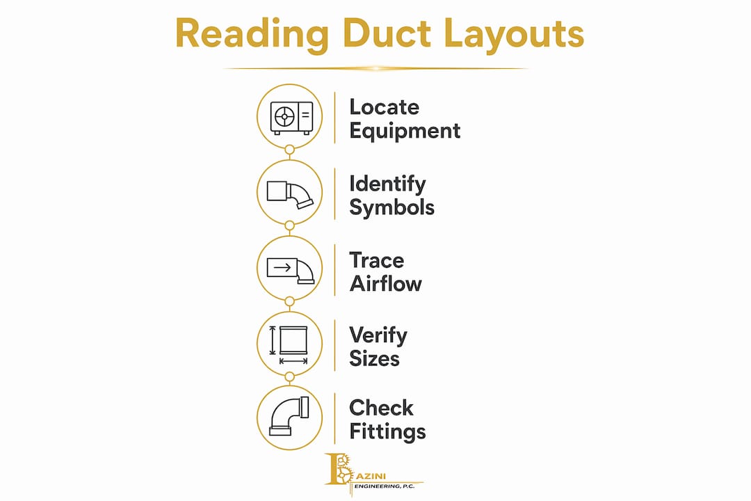
A structured workflow prevents the most common reading errors. Follow these steps every time you pick up a new set of HVAC installation drawings.
-
Identify all mechanical equipment. Locate the AHU, FCUs, exhaust fans, and any energy recovery units. Note their positions relative to the floor plan. Equipment location determines where main trunk ducts originate and which direction they run.
-
Trace the main supply trunk. Start at the AHU supply outlet and follow the largest duct run. The trunk reduces in size at each branch takeoff as air leaves the main stream. Confirm that each reduction is labeled and matches the sizing schedule.
-
Trace branch ducts to terminals. Follow each branch from the trunk to its supply diffuser or grille. Note the duct size at each segment. Verify that the CFM shown on the diffuser schedule matches what the branch duct can deliver at the target friction rate.
-
Locate all return and exhaust terminals. Return air paths are as critical as supply paths. Some drawings show dedicated return ducts; others rely on transfer grilles or door undercuts. Missing a return path causes pressurization problems and uneven comfort across zones.
-
Verify airflow direction arrows. Confirm that arrows on supply runs point away from the AHU and arrows on return runs point toward it. Any segment without a direction arrow needs clarification from the engineer of record before installation.
-
Cross-reference notes, legends, and schedules. Drawing notes often contain sleeve requirements, fire damper locations, and insulation specifications. Missing these details causes code violations and costly rework after walls close in.
| Step | Action | Common error to avoid |
|---|---|---|
| 1. Equipment identification | Locate AHU, FCU, fans on floor plan | Assuming equipment location without confirming |
| 2. Main trunk tracing | Follow supply trunk from AHU outward | Skipping size reductions at branch takeoffs |
| 3. Branch verification | Match branch CFM to diffuser schedule | Ignoring friction rate at reduced duct sizes |
| 4. Return path confirmation | Find all return grilles and transfer paths | Overlooking unlabeled transfer grilles |
| 5. Airflow direction check | Confirm all arrows match design intent | Reversing branch connections in the field |
| 6. Notes and schedules review | Read all drawing notes and legends | Missing fire damper or sleeve requirements |
What common mistakes should be avoided when reading duct drawings?
Errors in analyzing duct system drawings fall into predictable patterns. Knowing them in advance keeps your installation on track.
-
Skipping the legend. Every drawing set has one. Engineers use different line weights and symbol conventions. Reading a drawing without checking the legend first leads to misidentified duct types and reversed airflow paths.
-
Misreading duct size notation. A label of "12 x 8" means 12 inches wide by 8 inches tall, not the reverse. Swapping width and height changes the aspect ratio and the available cross-sectional area, both of which affect airflow.
-
Ignoring aspect ratio limits. Installers frequently misinterpret aspect ratios, causing excessive pressure drops that no amount of balancing can correct. SMACNA's 4:1 limit exists for a reason. A flat duct that fits a tight ceiling cavity may violate this limit and starve downstream terminals.
-
Overlooking fitting equivalent lengths. Field modifications without recalculating static pressure cause airflow starvation. Adding an elbow to route around an obstacle adds 30–50 feet of equivalent length. That change must be checked against the static pressure budget before the duct gets hung.
-
Missing return air paths. Ignoring return paths causes pressurization issues and uneven comfort. Drawings sometimes show returns only as dashed lines with no explicit label. Trace every dashed line back to the AHU to confirm the return system is complete.
-
Failing to coordinate with structural drawings. Duct routes conflict with structural elements when contractors skip cross-referencing. Beam pockets, joist depths, and ceiling cavity heights all constrain where ductwork can physically run. Flag conflicts during the submittal phase, not during installation.
"Missing sleeve or fire damper calls on duct drawings can cause costly rework and code violations. These details appear in drawing notes, not on the duct lines themselves, which is why contractors who skip the notes section consistently face field problems."
What I've learned from years of reading duct drawings in the field
The biggest misconception I encounter is that reading a duct layout drawing is just about tracking metal. Contractors who think that way focus on duct sizes and miss everything else. The drawing is actually a pressure map. Every symbol, every line type, and every annotation exists to communicate how air pressure moves through the system.
The submittal phase is where most problems get solved cheaply. When a contractor flags a structural conflict or a sizing discrepancy during submittal review, the fix costs a phone call and a revised drawing. The same fix during installation costs labor, materials, and schedule time. I have seen projects where skipping thorough submittal coordination added weeks to the construction timeline.
Return air design deserves the same attention as supply. Designers sometimes treat returns as an afterthought, and contractors follow that lead. A building where supply air is perfectly balanced but return paths are undersized will still have comfort complaints, pressurization noise, and door-slamming issues. Read the return system as carefully as the supply system.
Proactive communication between the design engineer, the installing contractor, and the general contractor resolves most interpretation conflicts before they become field problems. If a drawing note is unclear, ask the engineer of record before cutting metal. That conversation takes five minutes. The alternative takes five days.
— Joseph
Baziniengineering's mechanical engineering services for HVAC professionals
Accurate duct layout interpretation starts with drawings that are clear, coordinated, and code-compliant from the first issue.

Baziniengineering provides mechanical engineering design for commercial, residential, and institutional projects across New York City, Long Island, and Westchester County. The firm's HVAC duct design work follows ACCA Manual D sizing standards, SMACNA guidelines, and local code requirements, giving contractors drawings they can install with confidence. Baziniengineering coordinates duct layouts against structural and architectural drawings during the design phase, reducing field conflicts before they reach the job site. Contractors and builders who need permit-ready, installation-accurate HVAC drawings can contact Baziniengineering directly through the services overview page.
FAQ
What do solid and dashed lines mean in HVAC duct drawings?
Solid double lines represent supply air ducts, dashed lines represent return air ducts, and dot-dash lines represent exhaust ducts. Always confirm these conventions against the drawing legend, since individual engineers may vary the style.
What is the ACCA Manual D friction rate target?
The ACCA Manual D method targets a friction rate of 0.08 to 0.10 inches of water column per 100 feet of duct. Staying within this range prevents noise and maintains adequate airflow at every terminal.
Why does duct aspect ratio matter when reading drawings?
SMACNA limits duct aspect ratio to a maximum of 4:1 width to height. Exceeding this limit increases friction and pressure drop, which causes airflow starvation at downstream terminals even when duct dimensions appear correct on the drawing.
How do fittings affect duct sizing on layout drawings?
A single 90-degree elbow adds 30–50 feet of equivalent duct length to the static pressure calculation. Contractors must count all fittings along each branch run and verify that the total equivalent length stays within the static pressure budget shown on the drawings.
When should conflicts in duct drawings be flagged?
Conflicts between duct routes and structural elements should be flagged during the submittal review phase. Resolving conflicts before installation begins avoids field engineering deviations, material waste, and schedule delays.
Key takeaways
Professionals who follow a systematic, standards-based process when reading ductwork blueprints avoid the field conflicts, pressure imbalances, and code violations that derail HVAC installations.
| Point | Details |
|---|---|
| Read the legend first | Confirm all line types and symbols before tracing any duct run on the drawing. |
| Follow ACCA Manual D friction rates | Target 0.08–0.10 in. w.c. per 100 ft to keep airflow balanced and systems quiet. |
| Respect the 4:1 aspect ratio limit | Flat ducts that fit tight cavities may still violate SMACNA limits and cause pressure drops. |
| Count fitting equivalent lengths | Each elbow adds 30–50 ft of resistance; verify the static pressure budget holds after counting all fittings. |
| Trace return paths as carefully as supply | Unlabeled transfer grilles and door undercuts are part of the return system and must be confirmed on every drawing. |