
Water pressure in a building is not a single fixed value. It shifts constantly depending on elevation, flow demand, pipe size, and the mechanical systems working to keep it in range. At its core, building plumbing pressure is the force water exerts against pipe walls, measured in pounds per square inch (psi). Two distinct states govern every system: static pressure, which exists when no water is flowing, and dynamic pressure (also called residual pressure), which is the lower value measured during active flow. The gap between those two numbers tells you how much friction loss your system is carrying.
For multi-story buildings, the physics get complicated fast. Here are the foundational principles every building manager and engineer needs to understand:
- Municipal supply pressure typically arrives at the building meter within a range suitable for building supply, bounded by common regulatory maximums.
- Water pressure decreases by about 0.433 psi per vertical foot of elevation, which results in a loss of roughly 4.3 psi for every typical 10-foot floor height.
- Dynamic pressure is always lower than static pressure due to friction in pipes, fittings, and valves.
- A minimum dynamic pressure is needed to ensure acceptable fixture performance, as specified by plumbing codes.
- Booster pump systems are generally required for buildings taller than a few stories to maintain adequate pressure at upper floors.
- Pressure reducing valves (PRVs) are required by IPC §604.8 wherever static pressure exceeds 80 psi at any fixture.
How gravity and elevation drive pressure loss in tall buildings
Gravity is the dominant engineering challenge in any multi-story plumbing system due to the significant weight of water requiring pressure to lift it vertically. This means a relatively small amount of pressure corresponds to lifting water a few feet. In a building with typical floor heights, each story corresponds to a measurable pressure loss to overcome elevation.
The math becomes unforgiving quickly. A multi-story building experiences substantial pressure loss from ground to top floor due to elevation. If street pressure arrives at 60 psi, the top floor receives only about 17 psi before accounting for any friction losses, which is above the minimum dynamic pressure of 20 psi recommended for fixtures but close to the lower limit for acceptable operation. Upper-floor showers and flush valves are commonly affected by low pressure due to elevation losses.

How booster pump systems restore pressure
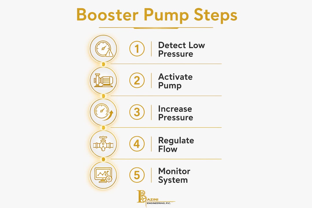
Booster pump systems are the standard solution for buildings where street pressure cannot reach upper floors. A typical configuration places the pump assembly in the basement or a mechanical room, drawing from the city main or a ground-level storage tank and pushing pressurized water up through a dedicated riser.
Modern high-rise installations rely on variable frequency drive (VFD) controlled pumps rather than constant-speed units. A VFD pump adjusts its motor speed in real time to match demand. During low-use overnight hours, it spins slowly and draws minimal power. During the morning peak when dozens of showers run simultaneously, it ramps up to maintain a preset system pressure. Constant-speed pumps, by contrast, run at full output regardless of demand, wasting energy and generating excess pressure that accelerates wear on valves and fittings.
Pro Tip: When specifying a booster pump, always verify the shutoff head. At near-zero flow, a constant-speed pump's pressure can spike well above its rated operating point. If that shutoff pressure exceeds the rated working pressure of your piping or fittings, you need either a VFD pump or a pressure relief valve on the discharge side.
For very tall structures, a single pump stage cannot cover the full height without creating dangerous overpressure at lower floors. The practical solution is a staged pumping arrangement: a lower pump serves the bottom half of the building and also feeds the suction side of a secondary pump that serves the upper half. This separation gives engineers independent pressure control over each building segment and simplifies maintenance isolation.
Gravity tank (downfeed) systems offer an alternative worth understanding. Transfer pumps fill a rooftop storage tank, and gravity distributes water downward through zone risers. Pressure is inherently stable because it depends only on tank elevation, not pump output. The tradeoff is structural load from the water tank and the maintenance requirement for periodic sediment flushing and tank inspection to prevent contamination.
| System type | Pressure stability | Power dependency | Maintenance focus |
|---|---|---|---|
| VFD booster (upfeed) | Excellent | Continuous | Pump, controls, PRVs |
| Constant-speed booster | Variable | Continuous | PRVs, pressure relief |
| Gravity tank (downfeed) | Constant | Intermittent | Tank cleaning, transfer pumps |
How PRVs and pressure zoning protect building plumbing systems
Even with a well-designed booster system, pressure distribution across a tall building creates a second problem: the lower floors of any pressurized zone receive far more pressure than the upper floors. Without intervention, ground-floor fixtures in a high-pressure riser zone could see pressures that destroy solenoid valves, water heaters, and fixture cartridges.
Pressure zone segmentation is the engineering answer. A tall building is divided into vertical bands, typically 6 to 15 floors per zone, each served by its own PRV station. The PRV station steps down the high-pressure riser supply to a zone-specific operating range. IPC §604.8 mandates PRV installation wherever static pressure at any fixture exceeds 80 psi. Good engineering practice targets a fixture pressure range below the code maximum to reduce wear and water hammer.
"Plumbing codes usually limit the high water pressure to 80 psi. Using 70 psi will result in more manageable flow rates at the fixtures, reduced water hammer, and lower velocities. These characteristics will result in lower operating costs and a longer life of the system." — PHCP Pros, High Rise Water Distribution
PRV types and how they work
Two PRV designs dominate commercial building applications:
Direct-acting PRVs use a spring-loaded diaphragm or piston. Downstream pressure pushes up against the diaphragm; the spring pushes down. When downstream pressure drops below the setpoint, the spring wins, the disc opens, and water flows. When pressure recovers, the diaphragm force closes the disc. These valves are simple, cost-effective, and the standard choice for most zones. A common configuration pairs two direct-acting PRVs in parallel, one sized for roughly one-third of peak flow and the other for two-thirds, which improves accuracy at low flow rates when the smaller valve handles regulation alone.
Pilot-operated PRVs add a small sensing valve that controls pressure in a chamber above the main diaphragm. Upstream pressure acts on both sides of the diaphragm, creating a balanced condition that makes the main valve more stable under fluctuating demand. These are preferred for large-diameter applications or zones with wide flow variation, where a direct-acting valve would hunt or chatter.
Pro Tip: Never install a PRV where supply pressure is already low. A PRV is a pressure-limiting device, not a booster. Installing one on a low-pressure supply worsens the problem by adding restriction. Measure static supply pressure at the meter first, then decide: if it is above 80 psi, use a PRV; if it is below the required minimum, use a booster pump.
Avoiding common plumbing code violations during PRV installation, such as omitting the required downstream pressure gauge or skipping the relief valve and indirect waste receptor, is as important as selecting the right valve type.
How pipe sizing and friction losses affect pressure throughout a building
Pipe diameter and flow velocity are where pressure management gets granular. Every foot of pipe, every elbow, every tee, and every valve adds friction resistance that reduces dynamic pressure. The cumulative effect of those losses determines whether a fixture at the end of a long branch run receives adequate pressure or a weak trickle.
Flow velocity in cold water supply piping is recommended to be kept within limits to reduce erosion and noise. Exceeding that threshold accelerates erosion of pipe walls and fittings, generates flow noise, and increases the risk of water hammer. Hot water systems are typically designed with lower maximum flow velocities to mitigate erosion. Undersized pipe forces velocity up; oversized pipe wastes material and reduces thermal performance in hot water lines.
Friction loss follows four primary mechanisms:
- Pipe wall resistance: proportional to velocity, pipe roughness, and run length. Older galvanized steel pipe has significantly higher roughness than copper or PEX.
- Elevation head loss: 0.433 psi per vertical foot, regardless of pipe size.
- Fitting and valve losses: expressed as equivalent pipe length added to straight-run calculations. A standard gate valve fully open adds minimal loss; a globe valve adds the equivalent of several feet of pipe.
- Velocity pressure loss: relevant at high-flow branch points where kinetic energy diverges from static pressure.
The Hazen-Williams equation is the standard tool for calculating friction loss in water supply piping. It relates flow rate, pipe diameter, pipe roughness coefficient (C-factor), and pipe length to produce a pressure drop per unit length. Copper type L carries a C-factor of approximately 130–140; galvanized steel drops to around 120 or lower with age. That difference translates directly into higher friction losses and lower dynamic pressure at fixtures in older buildings with corroded galvanized risers.
Pro Tip: When diagnosing low pressure at upper-floor fixtures, run a pressure gauge test at the fixture supply stop with flow running, not just at the meter with everything off. Static pressure at the meter can read a healthy 65 psi while dynamic pressure at the problem fixture drops below 20 psi due to undersized branch piping or excessive developed length.
| Pipe diameter | Typical max flow | Approximate friction loss per 100 ft at max flow |
|---|---|---|
| 3⁄4 inch copper | — | High |
| 1 in. copper | — | Moderate |
| 1½ inch copper | — | Lower |
| 2 in. copper | ~50 gpm | Low |
The distinction between static and dynamic pressure is especially important when evaluating branch runs. A system can pass a static pressure test at 70 psi and still fail to deliver adequate flow at a fixture when three or more branches open simultaneously. That simultaneous-use scenario is where Hunter's Curve calculations, as outlined in the ASPE Plumbing Engineering Design Handbook, determine whether your riser and branch sizing actually supports the fixture unit load.
Common water pressure problems in multi-story buildings and their causes
Low pressure on upper floors is the most frequent complaint building managers receive, and the cause is almost always one of three things: insufficient street pressure for the building height, an undersized or failing booster pump, or branch piping that was never sized for the actual fixture load. A building that performed adequately at four stories often shows pressure problems after a vertical addition or a change in occupancy that increases simultaneous demand.
Water hammer is a different category of problem entirely. It occurs when a fast-acting valve, typically a solenoid-operated valve in a dishwasher, washing machine, or HVAC system, closes suddenly and converts the kinetic energy of moving water into a pressure spike. That spike travels back through the piping as a shockwave, producing the characteristic banging noise and, over time, loosening fittings, cracking solder joints, and damaging valve seats. Systems operating at the upper end of the allowable pressure range are significantly more prone to water hammer because the spike magnitude scales with operating pressure.
"Water supply systems operating at higher than necessary pressure are more prone to water hammer. Systems that use fast-acting, solenoid-operated valves to allow or prevent water flow are also more prone to water hammer." — Caleffi, Plumbing System Pressure Concepts
Pressure fluctuations across the day, where fixtures deliver strong flow in the morning and weak flow at peak evening hours, point to a different mechanism: dynamic pressure loss in the municipal main. When neighborhood demand peaks, higher flow through the street main increases friction loss in the distribution system, reducing the pressure arriving at the building meter. A building relying entirely on street pressure with no booster or storage buffer will mirror those fluctuations directly at its fixtures.
Excessive pressure is an underappreciated failure mode. Fixtures, water heaters, and appliance solenoid valves carry rated working pressures, and operating above those ratings shortens service life and voids warranties. A supply arriving at 95 psi with no PRV installed exposes every downstream component to pressures that exceed their design tolerance. The IPC requires a PRV set to no more than 80 psi in that scenario, and good practice targets 70 psi or below.
Common warning signs worth tracking:
- Banging or knocking in walls after valve closure (water hammer)
- Pressure noticeably weaker on upper floors than lower floors
- Fixtures delivering a burst of flow when first opened, then settling to a lower rate (static-to-dynamic pressure drop)
- Leaking pressure relief valves on water heaters (overpressure)
- Rapid wear on fixture cartridges and valve seats (chronic overpressure or water hammer)
Maintenance, diagnostics, and modern tools for managing building pressure
Dynamic pressure testing during peak demand hours is the single most useful diagnostic tool available to building engineers. Static pressure readings at the meter tell you what the system can deliver at rest; they do not reveal friction losses in branch piping, partially closed isolation valves, or sediment-restricted PRVs. A gauge installed at the fixture supply stop during morning peak flow shows you exactly what the fixture actually receives.
A practical maintenance program for building plumbing pressure systems covers three categories:
Booster pump checks: Verify operating pressure at the pump discharge against the design setpoint. Listen for cavitation noise, which indicates insufficient suction pressure or a failing impeller. Check VFD fault logs for overcurrent events that signal pump strain. Confirm that standby pump alternation is functioning so wear distributes evenly across the pump set.
PRV inspection and adjustment: Test downstream pressure with a gauge at the zone riser after the PRV station. A PRV that has drifted above its setpoint needs adjustment or replacement. Sediment accumulation on the valve seat is a common cause of pressure creep in older systems. Pilot-operated PRVs require periodic cleaning of the pilot orifice, which can clog with mineral deposits.
Pipe and system checks: Flush low points and sediment traps annually. Inspect accessible copper and steel piping for signs of corrosion, pinhole leaks, or green staining that indicates active pitting. Verify that all isolation valves are fully open; a partially closed gate valve on a branch riser can produce pressure symptoms identical to an undersized pipe.
"Static pressure gauges alone are insufficient for diagnosing pressure issues; dynamic pressure measurement during peak flow is essential to detect hidden bottlenecks caused by deposits or undersized piping segments." — Caleffi, Plumbing System Pressure Concepts
Pro Tip: Install permanent pressure monitoring points at the top and bottom of each pressure zone, not just at the meter. A continuous pressure logger at the top-floor branch connection will catch PRV drift or pump degradation weeks before tenants start calling.
Electronic pressure monitoring systems now make continuous zone-level tracking practical for commercial buildings. These systems log pressure at multiple points, generate trend data, and can send alerts when pressure drops below or rises above preset thresholds. Combined with VFD booster pumps that already track system pressure electronically, they give building engineers a real-time picture of system health without manual gauge readings.

Gravity-fed downfeed systems require a specific maintenance focus: rooftop tank inspection and sediment flushing on a regular schedule. Sediment accumulation at the tank bottom can enter the distribution piping and accelerate PRV seat wear throughout the building. Tank liner integrity checks and water quality sampling should be part of any annual maintenance plan for gravity-fed systems.
Expert insights from Baziniengineering on managing plumbing pressure in multi-story buildings
Baziniengineering has designed and reviewed plumbing systems for multi-story commercial, residential, and institutional buildings across New York City, Long Island, and Westchester County since 2010. The pressure management challenges in that market are specific: aging municipal infrastructure with variable street pressure, buildings that were originally designed for lower occupancy loads, and local Department of Buildings inspection requirements that add a layer of documentation to every PRV and booster pump installation.
The most consistent finding across those projects is that fixture pressure targets matter more than code ceilings. IPC §604.8 permits up to 80 psi static pressure at fixtures, but Baziniengineering's design standard targets 50–70 psi. That 10 psi buffer below the code maximum reduces water hammer events, extends PRV and fixture cartridge life, and gives the system room to absorb pressure spikes from fast-acting solenoid valves without reaching damaging levels.
Pressure zone boundaries in NYC high-rise projects typically follow structural floor groupings rather than arbitrary floor counts. Mechanical rooms at transfer floors provide natural locations for PRV stations and booster pump sets, which simplifies maintenance access and keeps high-pressure risers short. For buildings over 15 stories, Baziniengineering's plumbing engineering services routinely include a full hydraulic analysis that models simultaneous demand across all zones, not just peak-floor calculations.
"The most common mistake we see in existing buildings is a PRV that was set correctly at installation and never touched again. Pressure setpoints drift, diaphragms fatigue, and pilot orifices clog. A PRV that reads 75 psi on the downstream gauge today may have been delivering 90 psi for the past two years." — Baziniengineering, MEP Engineering Practice
Pro Tip: For buildings in NYC with street pressures that vary seasonally, document static pressure at the meter in both summer and winter. Summer demand on the municipal main can reduce street pressure by 10–15 psi, which changes the boost pressure calculation for your pump system and may require seasonal setpoint adjustments.
Regional code compliance adds specificity to standard IPC requirements. New York City's Department of Buildings requires permit filings and inspections for booster pump installations and PRV replacements above certain thresholds. Rough-in inspections verify pipe sizing and valve placement before walls close; final inspections confirm operating pressure within the permitted range. Skipping those steps creates liability exposure and can complicate certificate of occupancy renewals for commercial tenants.
The sprinkler system design for a building also intersects with domestic water pressure management. Fire standpipe systems in high-rise buildings require 100 psi residual pressure at the highest outlet per NFPA 14, which is a separate hydraulic demand that must be isolated from the domestic water pressure zones. Coordinating those two systems during design prevents the pressure conflicts that show up as domestic pressure drops during fire system testing.

Baziniengineering provides full MEP/FP engineering design and consulting for buildings where pressure management is a core design challenge. Whether you are commissioning a new high-rise, troubleshooting chronic low pressure on upper floors, or navigating a NYC Department of Buildings permit for a booster pump replacement, the firm's engineering services cover the full scope from hydraulic analysis through permit expediting and inspection support.
Key Takeaways
Pressure in a building plumbing system is governed by elevation, friction, and the mechanical components that compensate for both. Managing it correctly requires understanding both static and dynamic pressure, not just what the meter reads at rest.
| Point | Details |
|---|---|
| Gravity loss per floor | Water pressure loss corresponds to vertical elevation and requires booster systems above a few stories. |
| Dynamic pressure minimum | Fixtures require at least 20 psi dynamic pressure during flow for acceptable performance, per plumbing code standards. |
| PRV code threshold | IPC §604.8 requires a PRV wherever static pressure exceeds 80 psi at any fixture; good practice sets the fixture pressure target between 50 and 70 psi. |
| Pressure zone depth | Buildings are segmented into zones of 6–15 floors, each served by a dedicated PRV station to keep fixture pressure in range. |
| Diagnostic priority | Static pressure at the meter does not reveal friction losses; dynamic pressure testing during peak flow is the reliable diagnostic method. |