
Available fault current comes from two calculations, not one: find the transformer's terminal short-circuit current using its kVA and %Z, then apply the point-to-point method to knock that number down as it travels through conductors to the panel or device you're rating. Once you have that final figure, NEC 110.9 requires the equipment's interrupting rating (AIC) or SCCR to meet or exceed it, full stop.
TL;DR:
- Transformer short-circuit current is calculated using kVA, %Z, and secondary voltage, then adjusted downstream with the point-to-point method to account for conductor impedance.
- Conductor length, size, and material significantly reduce available fault current at the panel, so accurate modeling of these factors is essential for proper protection sizing.
- Including motor and generator contributions increases fault current estimates, potentially requiring higher interrupting ratings for safety and compliance.
- Using utility fault current data and actual utility impedance can lower calculated fault levels compared to conservative infinite-bus assumptions, enabling more precise equipment ratings.
- When systems involve multiple power sources or tight margin conditions, a full short-circuit study is necessary instead of simple field calculations for code compliance and safety.
Table of Contents
- What Is Fault Current Calculation and Why the Formula Matters
- Quick Formulas for Transformer and Single-Line Fault Current
- How Do You Calculate Downstream Fault Current With the Point-to-Point Method?
- Why Utility Source Impedance Changes Your Fault Current Numbers
- How Conductor Length and Size Affect Fault Current
- Do Motors and Generators Add to Fault Current?
- What NEC Rules Govern Fault Current and Equipment Ratings?
- Worked Example: From Transformer Nameplate to Panel Fault Current
- Bazini Engineering's Practical Checklist for Verifying Fault Current
- When Do You Need a Full Short-Circuit Study Instead of a Field Check?
- Get a Site-Specific Fault Current Study From Bazini Engineering
- Standards and References Worth Keeping on File
- Sources
- FAQ
What Is Fault Current Calculation and Why the Formula Matters
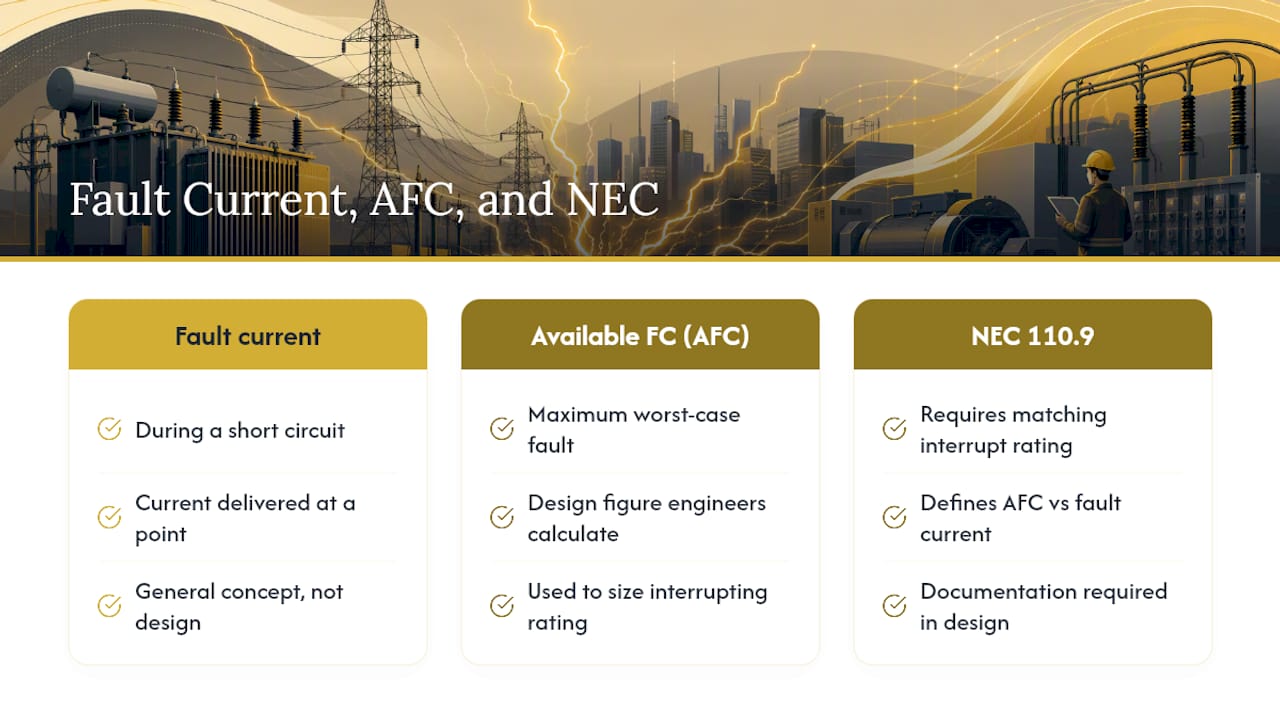
Fault current is the current a circuit delivers at a specific point during a short circuit. Available fault current (AFC) is the maximum version of that number, the worst case a protective device must be rated to interrupt safely. The National Electrical Code doesn't leave this to judgment. NEC 110.9 requires interrupting ratings to match or exceed available fault current, and NEC's definitions draw a hard line between "fault current" as a general concept and "available fault current" as the specific design figure engineers must calculate and document.
That distinction drives everything downstream. If you undersize a breaker's AIC rating relative to actual fault current, it can fail catastrophically instead of clearing the fault. This is why fault current calculation isn't optional paperwork. It's the number that determines whether your gear survives a fault or becomes part of the problem.
Quick Formulas for Transformer and Single-Line Fault Current
Every fault current calculation starts at the transformer, because that's usually where you have solid nameplate data to work with. The standard three-phase formula is:
Isc = (kVA × 1,000) / (√3 × Vsec × (%Z / 100))
For single-phase transformers, drop the √3 term: Isc = (kVA × 1,000) / (Vsec × (%Z / 100)).
A few practical notes before you run this:
- Pull kVA, secondary voltage, and %Z straight off the transformer nameplate. Don't estimate %Z; it varies by transformer size and design, and lower %Z always means higher available fault current.
- Note the winding configuration (delta-wye, wye-wye, etc.), since it changes how ground faults behave relative to phase faults.
- If you don't have utility source impedance data, assume an infinite bus. It's conservative and gives you a safe upper bound while you request real numbers.
How Do You Calculate Downstream Fault Current With the Point-to-Point Method?
Once you have transformer terminal Isc, you need to know what actually reaches the panel, disconnect, or receptacle you're protecting. Conductors add impedance, and impedance reduces fault current. The point-to-point method, drawn from the IEEE Red Book approach, is the field-standard way to calculate that reduction step by step.
- Start with the upstream available fault current (Isc_upstream), either the transformer terminal value or the output of the previous segment.
- Calculate the f-factor for the conductor run: f = (√3 × L × Isc_upstream) / (C × V), where L is conductor length in feet, C is the conductor constant from standard tables, and V is system voltage.
- Calculate the multiplier: M = 1 / (1 + f).
- Multiply: I_downstream = Isc_upstream × M.
- Repeat the sequence for each additional segment, using the previous segment's output as the new upstream value.
C constants come from published conductor tables and vary by material (copper vs. aluminum) and conduit type. Always use one-way conductor length, not the circuit's round-trip distance, and confirm whether your table already accounts for that.
Pro Tip: When a run has multiple sections with different conductor sizes, don't skip steps and calculate straight from source to endpoint. Run each segment separately and feed the output forward. Skipping segments understates impedance and overstates fault current at the far end, the opposite of what you want for a conservative calculation.
Why Utility Source Impedance Changes Your Fault Current Numbers
Assuming an infinite bus is fine for early screening, but it always overstates fault current, sometimes significantly. Real systems have finite utility source impedance, and folding that in gives you a more accurate, usually lower, number.
- If the utility gives you available fault current in kA at the service point, convert it to %Z referenced to your transformer's secondary voltage and kVA base, then combine it with the transformer's own %Z.
- Combined %Z is roughly the sum of source %Z and transformer %Z (both referenced to the same base), and the resulting Isc calculation using that combined value will always come out lower than the infinite-bus figure.
- Request a fault-current letter from the utility whenever the project allows it. It's the single fastest way to replace a conservative assumption with a real number, and many jurisdictions expect that documentation on file anyway.
Conservative practice defaults to infinite bus when utility data isn't available yet, then updates the calculation once real numbers arrive. Never treat the infinite-bus figure as final if a more accurate source impedance is obtainable.
How Conductor Length and Size Affect Fault Current
Every foot of conductor between the source and the fault point adds impedance, and impedance is what drives the point-to-point reduction. Longer runs and smaller conductors both increase the f-factor, which lowers the M multiplier and reduces available fault current at the far end.
- Pull conductor R and X values from NEC Chapter 9 tables or IEEE guidance, and account for operating temperature since resistance rises with heat.
- A long feeder, say 300 feet of small-gauge conductor, can cut available fault current by a meaningful percentage compared to the transformer terminal value; short runs on large conductors barely move the number at all.
- Parallel conductors reduce effective impedance proportionally, which means parallel runs increase available fault current, not decrease it. Model each parallel set as a single conductor with impedance divided by the number of parallel runs.
Conductor attenuation matters most for equipment sitting far from the transformer. Skip it near the source and you'll oversize protection; skip it downstream and you'll undersize it.
Do Motors and Generators Add to Fault Current?
Yes, and ignoring rotating machinery is one of the more common ways engineers understate available fault current. Running induction motors typically contribute roughly 4 to 6 times their full-load current during the first few cycles of a fault, and synchronous machines can contribute even more depending on their subtransient reactance.
For preliminary screening, estimate motor contribution roughly as a multiple of full-load current rather than modeling every motor individually. For standby or cogeneration systems, estimate generator contribution based on subtransient reactance from the generator nameplate. Both additions raise the fault current the breaker actually sees, which can push required AIC ratings higher and affect coordination.
What NEC Rules Govern Fault Current and Equipment Ratings?
Calculating the number is half the job. NEC 110.9 requires equipment intended to interrupt fault current, breakers, fuses, to have an interrupting rating equal to or greater than the available fault current at that point. NEC 110.10 requires the entire system, including SCCR-rated components like panelboards and motor control centers, to be able to withstand the let-through energy of a fault without hazardous damage. NEC 110.24 requires service equipment to be field-marked with the available fault current and the calculation date.
If your calculated AFC exceeds a device's AIC rating, you have two paths:
- Replace the device with one rated for the actual fault current, the straightforward fix in most cases.
- Explore a series rating with the manufacturer, which lets a lower-rated downstream device work safely behind a higher-rated upstream device, but only under tested and listed combinations.
Keep a documentation file for every calculation: the date, the engineer's signature, the assumptions used (infinite bus vs. utility data, motor contribution included or excluded), and the final AFC. Inspectors ask for this, and it protects you if system conditions change later.
Worked Example: From Transformer Nameplate to Panel Fault Current
Here's a full calculation strung together, start to finish, using realistic values.
- Transformer data: 750 kVA, 480V secondary, 5.75% impedance. Utility provides an available fault current of 22,000A at the primary service point.
- Transformer terminal Isc (infinite bus): Isc = (750 × 1,000) / (√3 × 480 × 0.0575) = approximately 15,700A.
- Adjust for utility source impedance: Converting the utility's 22,000A to %Z and combining with the transformer's 5.75% typically pulls the terminal figure down to somewhere in the 14,000 to 15,000A range, a meaningful drop from the infinite-bus assumption.
- Apply point-to-point for a 150-foot, 4/0 copper feeder at 480V: Using standard C constants, this segment's M multiplier typically lands around 0.85 to 0.90, bringing panel-level available fault current to roughly 12,000 to 13,000A.
- Compare to equipment rating: A panel with a 14,000A SCCR clears this with margin. A panel rated at 10,000A does not, and needs replacement or a documented series rating before it goes into service.
That final panel figure, not the transformer terminal number, is what gets compared against the installed device's AIC or SCCR. Using the infinite-bus number alone would have you sizing equipment for a fault current higher than what the system can actually deliver, safe, but potentially an unnecessary cost.
Bazini Engineering's Practical Checklist for Verifying Fault Current
Bazini Engineering, P.C. is a professional engineering firm specializing in mechanical, electrical, plumbing, and fire protection design across commercial, residential, institutional, and industrial projects. Founded in 2010, the firm handles HVAC design, plumbing systems, fire suppression and alarm coordination, energy code compliance, and permit expediting with agencies including the NYC Department of Buildings and FDNY. Licensed in New York and Florida, the firm works throughout New York City, Long Island, and Westchester County. Field verification typically means confirming nameplate data against as-built conditions, checking for utility system upgrades since the last study, and flagging any equipment where calculated AFC sits close to its rated AIC.
When Do You Need a Full Short-Circuit Study Instead of a Field Check?
Point-to-point calculations work fine for screening, service marking, and small modifications. Once you're dealing with parallel utility sources, multiple generators, tight coordination margins, or equipment operating close to its rated AIC, a multi-bus software study becomes worth the cost. The field method is a good filter for catching problems early, not a substitute for engineering judgment when the stakes are high.
— Joseph
Get a Site-Specific Fault Current Study From Bazini Engineering
Point-to-point math gets you a solid screening number, but a stamped, code-compliant fault current study for permit submission is a different deliverable, one that accounts for your actual utility data, as-built conductor runs, and equipment schedule. Baziniengineering handles that work directly: fault current calculations, NEC-compliant documentation with proper service marking, field verification against existing gear, and permit expediting support with the NYC Department of Buildings and FDNY.

If your project involves new service equipment, a panel upgrade, or a Local Law 97 retrofit that touches electrical distribution, get the calculation done right the first time. Reach out through Bazini Engineering's mechanical and electrical services page to scope a site-specific fault current study, or browse the full service offerings to see where fault current documentation fits into your broader project needs.
Standards and References Worth Keeping on File
For methodology and verification, keep NEC 110.9, 110.10, and 110.24 on hand alongside the IEEE 141 (Red Book) point-to-point approach and IEC 60909 for full symmetrical and peak-current methods. Always request a utility fault-current letter when a project timeline allows it.
Sources
- Calculating short-circuit current — IAEI Magazine (2015)
- Short-circuit current calculations — Eaton technical library
FAQ
How Do You Calculate Fault Current for a Ground Fault?
Ground fault current depends heavily on system grounding configuration; solidly grounded systems generally produce ground fault currents close to phase fault magnitude, while high-resistance grounded systems intentionally limit ground fault current to a few amps. Use the same point-to-point approach but substitute zero-sequence impedance values where your system grounding type requires it.
Is There an Excel Template for Fault Current Calculations?
Spreadsheet templates exist for both the transformer Isc formula and the point-to-point method, and many engineers build their own using the equations in this article. For anything beyond simple screening, a dedicated calculator or full study software reduces the risk of formula errors.
How Do You Calculate Full-Load Current (FLC)?
Full-load current for a three-phase load is FLC = (kVA × 1,000) / (√3 × V), or for motors, pull the value directly from the nameplate. FLC matters for fault current work because motor contribution is typically estimated as a multiple of FLC.
How Do You Calculate Fault Current for a Transformer?
Use Isc = (kVA × 1,000) / (√3 × Vsec × (%Z / 100)) for three-phase transformers, pulling kVA, secondary voltage, and %Z from the nameplate. This gives you the infinite-bus terminal value; adjust it downward once you have actual utility source impedance data.